Rating:
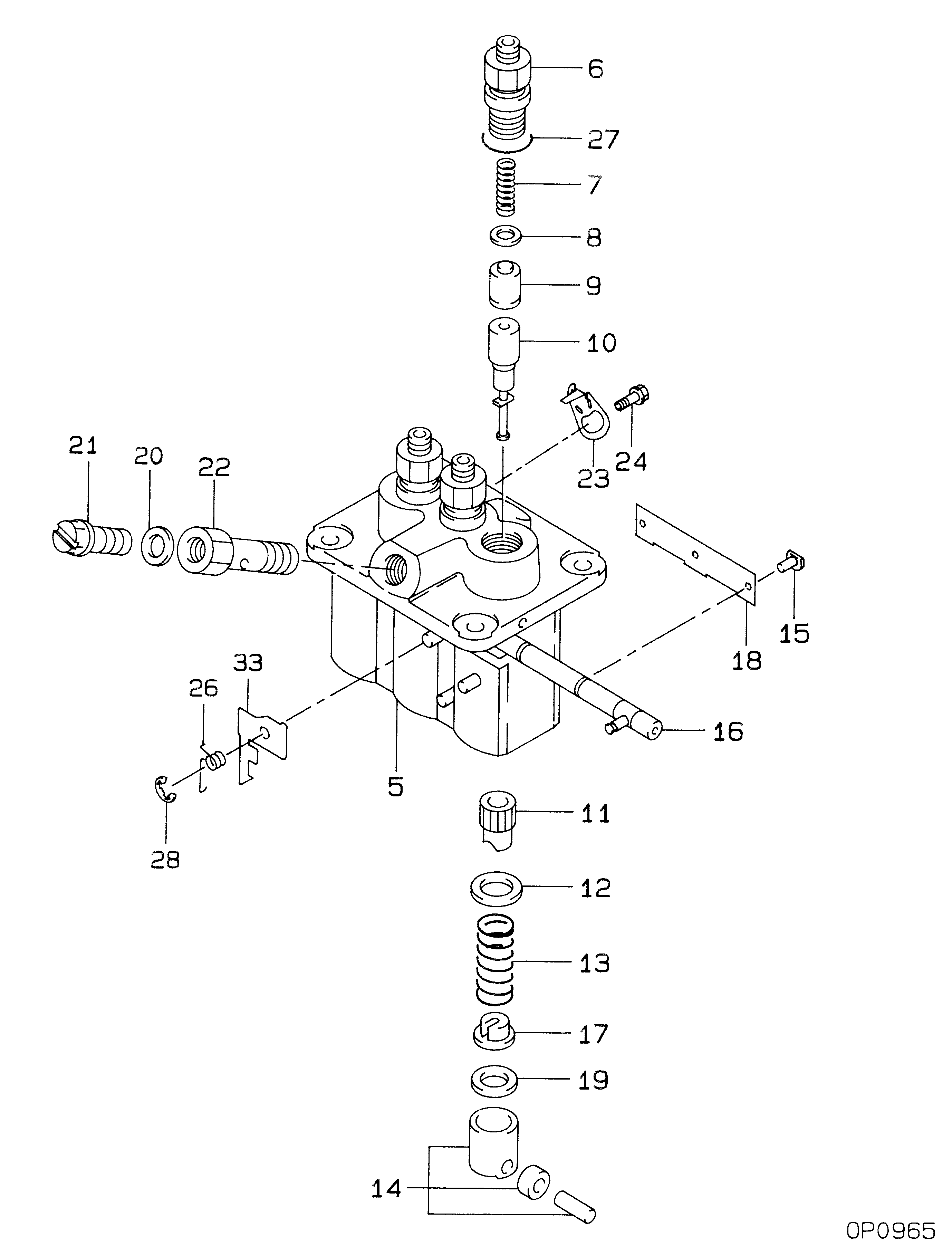
Information pump assy, injecti Denso
Product
Fuel Injection Pump
Vehicle engine
MARINE K3F-61WM
Engine
K3F-61WM
Serial start-end
9605-
Info
Injector Nozzle
093500-1660
Injector nozzle:
0935001660
Components :
Scheme #.#:
№
Qty
Part num
Name
Remarks
Manufacture num
Cross reference number
Part num
Firm num
Firm
Name
09450-06950
PUMP ASSY, INJECTI


Information:
Replacing the SLC 5/04
To avoid damage to electronic components, do not remove the processor from the SLC 5/04 Chassis until all power is removed from the power supply.Do not expose memory modules to surfaces or areas that may typically hold an electrostatic charge.
Disconnect the power supply.
Press the retaining clips at the top of the module and press the retaining clips at the bottom of the module.
Remove the processor from the chassis.
Disconnect the Battery by removing the battery connector from the socket.
To avoid potential damage to the processor, handle all modules by the ends of the carrier or edges of the plastic housing. Skin oil or dirt can corrode metallic surfaces, inhibiting electrical contact.
Connect the battery and the processor by attaching the battery connector to the socket.
Align the processor and the guides in the chassis.
Gently slide the module in the chassis. Secure the top retainer clips and secure the bottom retainer clips.
Install a wire tie in order to secure the wiring.
Cover any unused slots. This protects the chassis.
Illustration 1 g00563306
Verify that the new processor corrects the problem.