Rating:
Information pump assy, injecti Denso
Product
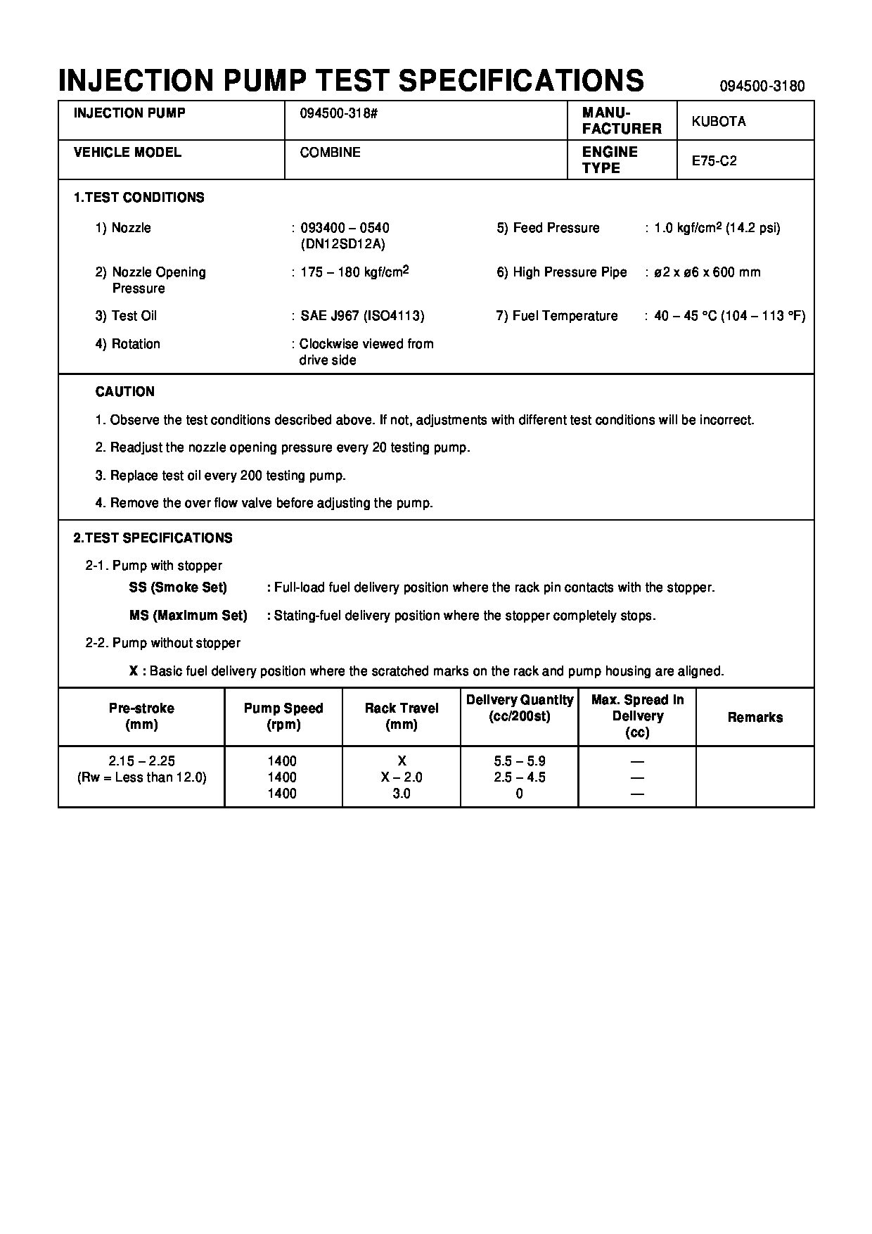
Fuel Injection Pump
Vehicle engine
COMBINE E75-C2
Engine
E75-C2
Serial start-end
8406-
Info
Injector Nozzle
093500-1930
Injector nozzle:
0935001930
Components :
Scheme #.#:
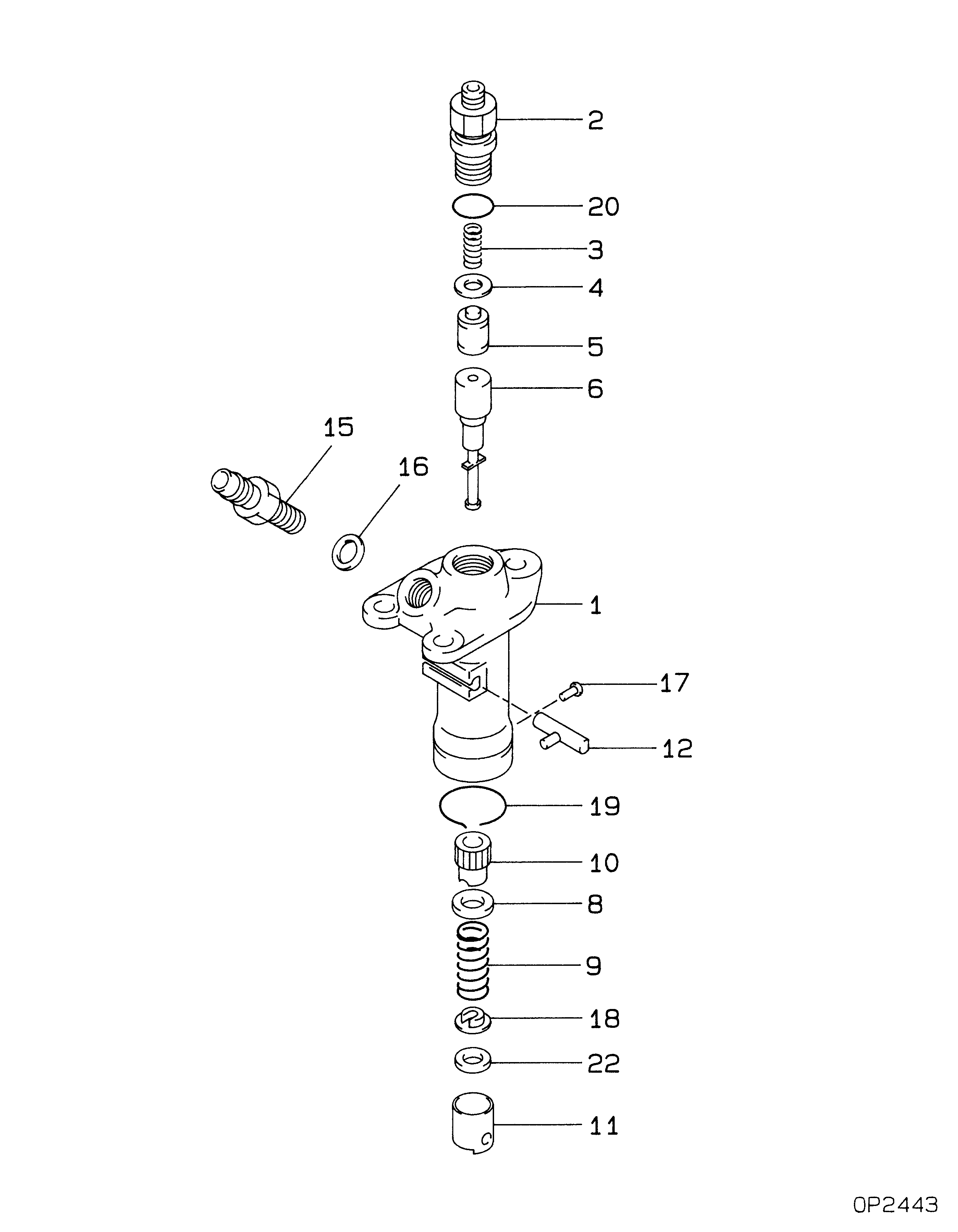
№
Qty
Part num
Name
Remarks
Manufacture num
Cross reference number
Part num
Firm num
Firm
Name
09450-03180
PUMP ASSY, INJECTI
0945003180
14287-51011
KUBOTA
PUMP ASSY, INJECTI

Information:
System Operation
The SLC 5/04 diagnostic indicators are located on the front of the following components: Power Supply, CPU and I/O Modules.The diagnostic indicators help trace the source of the fault. Faults can be found in the following components: Input devices, Output devices, Wiring and The controller.The battery is a replaceable lithium battery. The battery provides backup power for approximately two years. The "BATT" LED on the front of the processor alerts you when the battery voltage has fallen below a threshold level.The red "FLT" LED is flashing during operation. The processor detects a major fault. The fault is in the processor expansion chassis or the fault is in the memory.The red "BATT" LED is illuminated. The battery voltage has fallen below a threshold level.The red "BATT" LED is not illuminated. The battery is functional.
Illustration 1 g00563546
Diagram of the LED indicators
Illustration 2 g00563548
Functional Test
Check the electrical connectors and check the wiring.
Bodily contact with electrical potential can cause bodily injury or death.To avoid the possibility of injury or death, ensure that the main power supply has been disconnected before performing any maintenance or removing any modules.
Disconnect the power supply.
Check the electrical connectors and check the wiring for damage or bad connections.
Verify that all modules are properly seated.
Verify the status of the LED on the SLC 5/04.The results of the preceding procedure are in the following list:
All of the components are fully installed. All of the components are free of corrosion. All of the components are free of damage. All of the modules are properly seated. Proceed to 2.
The components are not fully installed. The components are not free of corrosion. The components are damaged. All of the modules are not properly seated. Repair the component. Verify that the repair resolves the problem. STOP.
Verify that the battery is connected.
Verify that the battery is properly connected.The results of the preceding procedure are in the following list:
The battery is properly connected. Replace the battery. Verify that the repair resolves the problem. Refer to Maintenance Procedure, "Battery - Replace". Stop.
The battery is not properly connected. Proceed to 3.
Replace the battery.
To avoid damage to electronic components, do not remove the processor from the SLC 5/04 Chassis until all power is removed from the power supply.Do not expose memory modules to surfaces or areas that may typically hold an electrostatic charge.
Secure power to the processor.
Press the retaining clips at the top of the processor and press the retaining clips at the bottom of the processor.
Remove the processor from the chassis.
To avoid potential damage to the processor, handle all modules by the ends of the carrier or edges of the plastic housing. Skin oil or dirt can corrode metallic surfaces, inhibiting electrical contact.
Disconnect the battery. Remove the battery.
Install the new battery. Connect the new battery.
Align the processor and the guides in the chassis.
Gently slide the processor in the chassis. Secure the top retainer clips and secure the bottom retainer clips.
Install a wire tie in order to secure the wiring.The results of the preceding procedure are in the following list:
No