Rating:
Information pump assy, injecti Denso
Product
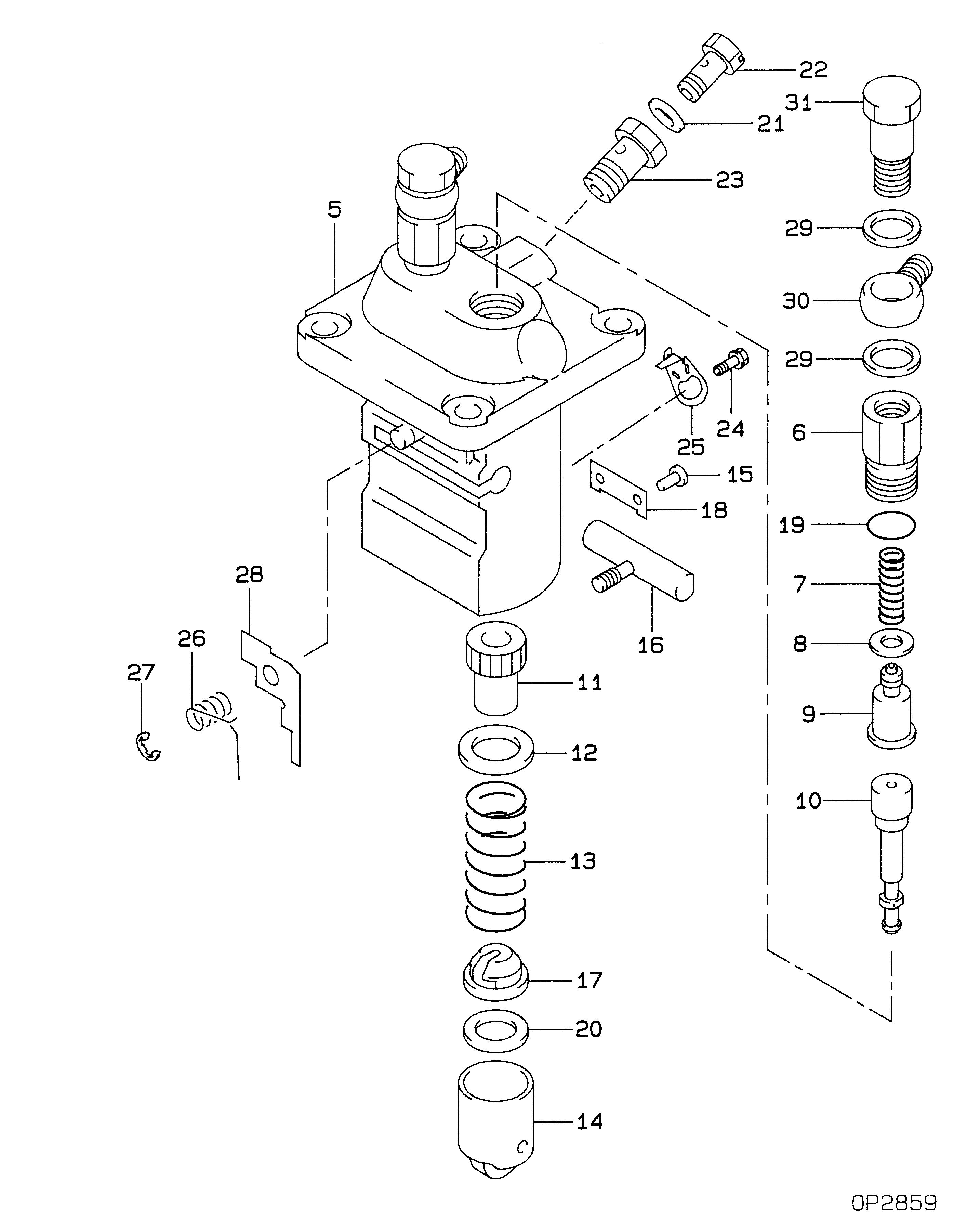
Fuel Injection Pump
Vehicle engine
INDUSTRIAL SDT130
Engine
SDT130
Serial start-end
7903--8001
Info
Injector Nozzle
093500-1110
Injector nozzle:
0935001110
Components :
Scheme #.#:
№
Qty
Part num
Name
Remarks
Manufacture num
000
[01]
09450-01660
PUMP ASSY, INJECTI
PFR2K
Include in ##:
09450-01660
as PUMP ASSY, INJECTI
Cross reference number
Part num
Firm num
Firm
Name
09450-01660
PUMP ASSY, INJECTI
Information:
1. Remove the plug, and move the race until Tool (A) can be installed to hold the rack in the center position. The rack must be in the center position to remove the fuel injection pumps.
To prevent possible personal injury carefully follow the steps below.
2. Put Tool (B), except for the 8T5287 Wrench, in position on the fuel pump housing as shown. Lower the handle to center the adjusting screw with the fuel line seat. With the handle down in the locked position, the adjusting screw must just be in contact with fuel line seat (1). If force is needed to lower the handle or there is a gap, remove the tooling, and make an adjustment to the screw.3. Loosen bushing (2) 1/4 of a turn.4. Put Tool (B) in position on the pump housing with the handle down in the locked position as shown.5. Remove bushing (2) from the pump housing.6. Carefully and slowly lift the handle to release the spring force. Remove the tooling. 7. Install Tool (C) on fuel pump (4) as shown.8. Remove seal (3) and fuel pump (4) from the fuel pump housing. 9. Remove spacers (5) from the pump housing. There must be a pump installed on either side of the pump to be removed to install Tool (B). If there is no pump, take a pump already removed, and remove the spring so there will be no spring force, and install it in the pump housing. See Install Fuel Pump. Spacers (5) are the same thickness for each fuel injection pump so they can be mixed. The fuel injection pump plungers and barrels are sets and cannot be mixed.Install Fuel Injection Pumps
1. Install spacers (5) in the fuel pump housing.2. Move the rack until Tool (A) can be installed to hold the rack in the center position. The rack must be in the center position to install the fuel injection pumps.3. Install a fuel pump without its spring so that Tool (B) can be installed. See Step 5 for correct fuel pump installation. 4. Install Tool (C) on the bonnet of the fuel pump as shown.5. Install the fuel pump in the pump housing with the saw cut (slot) (9) in the gear in alignment with small pin (6) in the lifter assembly and groove (8) in the barrel in alignment with large pin (7) in the pump housing. 6. Install the seal and bushing (2) on the fuel pump.7. Put Tool (B) in position on the fuel pump housing as shown.8. Lower the handle slowly and carefully. If the fuel pump is not installed correctly, the handle will not go all the way down. Do not try to use force on it. Remove and install the tooling and the fuel pump again.9. Make sure the seal is in its correct position, and start to tighten bushing (2). Remove the tooling, and tighten the bushing to a torque of 260 15 N m (190 10 lb ft). Back off