Rating:
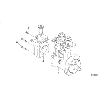
Information pump assy, supply Denso
Product
Fuel Injection Pump
Vehicle engine
TRUCK E13C
Engine
E13C
Serial start-end
1805-
Info
Injector Nozzle
HINO
PUMP ASSY, SUPPLY
DA
- * DMCF DENSO PRODUCTION CW094000-103#
Components :
Scheme #.#:
№
Qty
Part num
Name
Remarks
Manufacture num
Cross reference number
Part num
Firm num
Firm
Name
09400-01030
HINO
PUMP ASSY, SUPPLY
0940001030
22100-E0303
HINO
PUMP ASSY, SUPPLY
Information:
1. Drain the coolant from the cooling system into a suitable container for storage or disposal. 2. Loosen bolts (1) and (2) on water pump drive (3).3. Remove V-belt (4) from the drive pulley on the water pump and the pulley on the water pump drive.4. Remove two hose clamps (5). Disconnect the hose used between the water pump and the water temperature regulator housing at the water pump.5. Remove four bolts (6) that hold the water pump to the front of the engine. Carefully remove the water pump and two O-ring seals from the front of the engine. The following steps are for the installation of the water pump.6. Check the condition of the two O-ring seals used between the water pump and the cylinder block. If the seals are damaged, use new parts for replacement.7. Install the two O-ring seals in the cover of the water pump. Put the water pump in position on the front of the engine, and install four bolts (6) that hold it.8. Connect the short hose used between the water pump and the water temperature regulator housing to the water pump. Install two clamps (5) that hold the hose in position.9. Put V-belt (4) in position on the water pump drive pulley and the pulley on water pump drive.10. Adjust the tension of water pump drive V-belt (4). Bolt (7) or square hole (8) are used to apply and hold V-belt tension. See the topic "Alternator And Fan Drive Belts, Inspect/Adjust/Replace" in the 3114 & 3116 ATAAC Diesel Truck Engine Operation & Maintenance Manual, Form No. SEBU6723. Also, refer to the "Belt Tension Chart" in the 3114 & 3116 Diesel Truck Engines Specifications module, Form No. SENR6436.11. Fill the cooling system with coolant to the correct level. See the topic "Cooling System" in the 3114 & 3116 ATAAC Diesel Truck Engine Operation & Maintenance Manual, Form No. SEBU6723.Disassemble & Assemble Water Pump
Start By:a. remove water pump 1. Remove two O-ring seals (1) from the rear cover of the water pump. Remove four bolts (2) and the washers. Remove the rear cover and gasket. 2. Put the water pump in a press. Use spacer plates to level the water pump as shown.3. Using a suitable size drive plate from Tool (A) and a press, push the shaft and pulley (3), as a unit, out of impeller (4). Remove the impeller.
Do not allow the shaft and pulley to fall to the floor as it is being removed from seal (5) and the water pump housing. Damage to the shaft and pulley will result.
4. Continue to push the shaft and pulley out of seal (5) and the water pump housing. 5. Using the handle from Tool (B) and a press, remove seal (5) from the water pump housing. 6. Using a press, remove the shaft and bearing assembly from pulley (3). The following steps are for the assembly of the water pump. 7. Using a press, install the shaft and bearing assembly into pulley


