Rating:
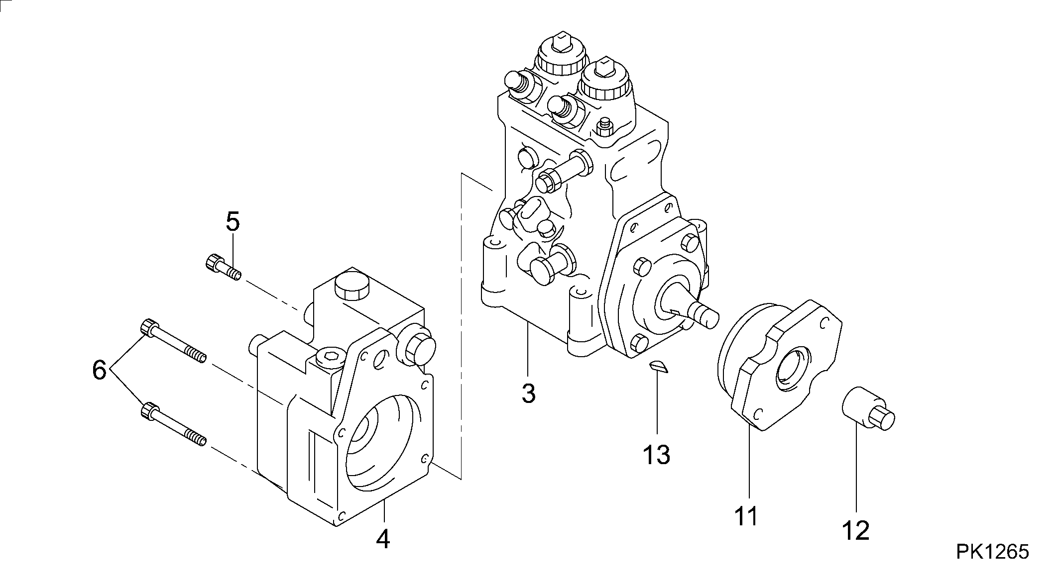
Information pump assy, supply Denso
Compare Prices: .
As an associate, we earn commssions on qualifying purchases through the links below

BCXFORK Denso Fuel Injection Pump 094000-0722 8-97625496-3 for Isuzu Engine 6UZ1 6TE1
BCXFORK NOTE Before placing an order, please verify that your part number matches the one in the listing. Some fuel injection pump may look similar. If you're unsure, you can leave us a message and provide a picture of your old fuel injection pump for verification. || Package Include: 1 x Fuel Injection Pump || Part Number: 094000-0722, 094000-0720, 8-97625496-0, 8-97625496-3, 094000-0721, 0940000722, 0940000720, 8976254960, 8976254963, 0940000721 || This item fits for Isuzu Engine 6UZ1 6TE1; fits for Komatsu Excavator: PC400-7, PC450-7, PC400-8, PC450-8
BCXFORK NOTE Before placing an order, please verify that your part number matches the one in the listing. Some fuel injection pump may look similar. If you're unsure, you can leave us a message and provide a picture of your old fuel injection pump for verification. || Package Include: 1 x Fuel Injection Pump || Part Number: 094000-0722, 094000-0720, 8-97625496-0, 8-97625496-3, 094000-0721, 0940000722, 0940000720, 8976254960, 8976254963, 0940000721 || This item fits for Isuzu Engine 6UZ1 6TE1; fits for Komatsu Excavator: PC400-7, PC450-7, PC400-8, PC450-8

Diesel Oil Pump Model: 094000-0720 094000-0722 8-97625496-0 8-97625496-3
WSVKJLGR Tip: Before placing your order, please carefully check and confirm that the model and part number of the fuel injection pump you order matches the specifications of your specific equipment. || Simple installation: reasonable design and simple installation steps to ensure the normal function of the fuel injection pump. || Precise control: Precise control of fuel flow makes engine power output more stable. || Stable pressure: stable output of fuel pressure under various working conditions to ensure continuous and stable operation of the engine. || High-precision injection: The injection pump adopts advanced technology to achieve high-precision fuel injection to ensure full fuel combustion and improve engine performance.
WSVKJLGR Tip: Before placing your order, please carefully check and confirm that the model and part number of the fuel injection pump you order matches the specifications of your specific equipment. || Simple installation: reasonable design and simple installation steps to ensure the normal function of the fuel injection pump. || Precise control: Precise control of fuel flow makes engine power output more stable. || Stable pressure: stable output of fuel pressure under various working conditions to ensure continuous and stable operation of the engine. || High-precision injection: The injection pump adopts advanced technology to achieve high-precision fuel injection to ensure full fuel combustion and improve engine performance.

You can buy:

Include in ##:
Cross reference number
Part num
Firm num
Firm
Name
09400-00722
8-97625496
PUMP ASSY, SUPPLY
Information:
2. Loosen bolt (1) until there is approximately 3.18 mm (.125 in) gap between washer (2) and fuel pump drive gear (3).3. Install Tool (C) as shown, and loosen the fuel pump drive gear from the taper on the fuel injection pump camshaft. Remove Tool (C), the bolt, washer and fuel pump drive gear.4. Remove the bolts and plate (4) that hold idler gear (5) in position. Remove the idler gear. If necessary, remove the bearing from the idler gear with Tool (D) and a press.
Do not turn the crankshaft after camshaft gear (6) has been removed. Turning the crankshaft will cause damage to the valves.
5. Remove the four bolts that hold camshaft gear (6) to the camshaft. Remove the camshaft gear.Install Timing Gears
1. Make an alignment of the "C" marks on crankshaft gear (3) and camshaft gear (4). Install the camshaft gear and the bolts that hold it. Tighten the bolts to a torque of 55 7 N m (41 5 lb ft).2. Install the bearing in idler gear (1) with Tool (A). The end of the bearing must be 1.52 mm (.060 in) below the face of the gear hub after installation.3. Be sure the oil hole in the shaft for idler gear (1) is open. Put idler gear (1) and plate (2) in position on the shaft. Install the bolts that hold them. 4. Make sure Tool (C) is in position in the groove of the fuel injection pump camshaft.5. Put fuel injection pump drive gear (5) in position on the fuel injection pump camshaft. Put washer (6) in position on the gear with the largest diameter toward the front of the engine. Install bolt (7), and tighten it to a torque of 7 N m (5 lb ft). Make sure bolt (7) does not turn while the flywheel is being turned.6. Remove the timing bolt from the flywheel, and use Tool (B) to turn the flywheel in the opposite direction of engine rotation. Turn the flywheel until the "C" mark on the crankshaft gear moves 30°.7. Turn the flywheel in the direction of engine rotation until the timing bolt can be installed in the flywheel and the "C" marks are in alignment. This will remove all of the backlash from the timing gears.8. Tighten bolt (7) to a torque of 270 25 N m (199 18 lb ft).9. Remove Tool (B) and (C). Remove the timing bolt from the flywheel. Install the covers on the flywheel housing and fuel injection pump housing. Install the plug in the flywheel housing.End By:a. install timing gear cover