Rating:
Information pump assy, supply Denso
Product
Fuel Injection Pump
Vehicle engine
TRUCK D12
Engine
D12
Serial start-end
0809-
Info
Injector Nozzle
Product
Fuel Injection Pump
Vehicle engine
TRUCK D12
Engine
D12
Serial start-end
1001-
Info
Injector Nozzle
Compare Prices: .
As an associate, we earn commssions on qualifying purchases through the links below

Fuel Injection Pump 094000-0710 VG1246080050 For Sinotruck D12 Howo A7 Engine
oiasdfhjdg Product name:Fuel Injection Pump || Part Number:094000-0710 VG1246080050 || APPlication:For Sinotruck D12 Howo A7 Engine || 1.Please carefully compare the OE numbers before purchasing the product to match your original parts and avoid wasting your valuable time. || 2.Please ensure to provide us with the correct, accurate, and detailed delivery address and contact information
oiasdfhjdg Product name:Fuel Injection Pump || Part Number:094000-0710 VG1246080050 || APPlication:For Sinotruck D12 Howo A7 Engine || 1.Please carefully compare the OE numbers before purchasing the product to match your original parts and avoid wasting your valuable time. || 2.Please ensure to provide us with the correct, accurate, and detailed delivery address and contact information

HP0 Fuel Injection Pump for D12 Truck Sinotruck Howo A7 Engine 094000-0710 094000-0711 VG1246080050
KoovDem Part Number: 094000-0710, 094000-0711, VG1246080050. || Compatible Model: For D12 Truck Sinotruck Howo A7 Engine. || Effective and Reliable: Utilizing cutting-edge technology, this system delivers effective and reliable fuel supply, guaranteeing smooth vehicle performance. || Rugged and Dependable: With a track record of being rigorously tested and proven, this product offers durability and reliability, ensuring it operates consistently even in the harshest of environments. || Straightforward Installation: With a user-friendly interface, installing this product is a breeze. Simply plug it in and you're good to go, no technical expertise needed.
KoovDem Part Number: 094000-0710, 094000-0711, VG1246080050. || Compatible Model: For D12 Truck Sinotruck Howo A7 Engine. || Effective and Reliable: Utilizing cutting-edge technology, this system delivers effective and reliable fuel supply, guaranteeing smooth vehicle performance. || Rugged and Dependable: With a track record of being rigorously tested and proven, this product offers durability and reliability, ensuring it operates consistently even in the harshest of environments. || Straightforward Installation: With a user-friendly interface, installing this product is a breeze. Simply plug it in and you're good to go, no technical expertise needed.

New Fuel Injection Pump Solarhome 094000-0710 0940000710 Compatible With Sinotruk Howo Truck A7 Engine D12
EWAIDI Part Number: 094000-0710 0940000710 || Application: Compatible With Sinotruk Howo Truck A7 Engine D12 || Upgrade your vehicle with our Advanced Fuel Injection Pump for enhanced power and improved fuel economy. This high-performance pump delivers increased efficiency and precision, resulting in smoother fuel delivery for optimal engine performance. Trust in its cutting-edge technology to reduce emissions and improve gas mileage, keeping your engine running at peak performance. || Package includes: 1X Fuel Injection Pump with the part number 094000-0710.
EWAIDI Part Number: 094000-0710 0940000710 || Application: Compatible With Sinotruk Howo Truck A7 Engine D12 || Upgrade your vehicle with our Advanced Fuel Injection Pump for enhanced power and improved fuel economy. This high-performance pump delivers increased efficiency and precision, resulting in smoother fuel delivery for optimal engine performance. Trust in its cutting-edge technology to reduce emissions and improve gas mileage, keeping your engine running at peak performance. || Package includes: 1X Fuel Injection Pump with the part number 094000-0710.
You can buy:

$1219.85
23 Nov 2023
Components :
Scheme #.#:
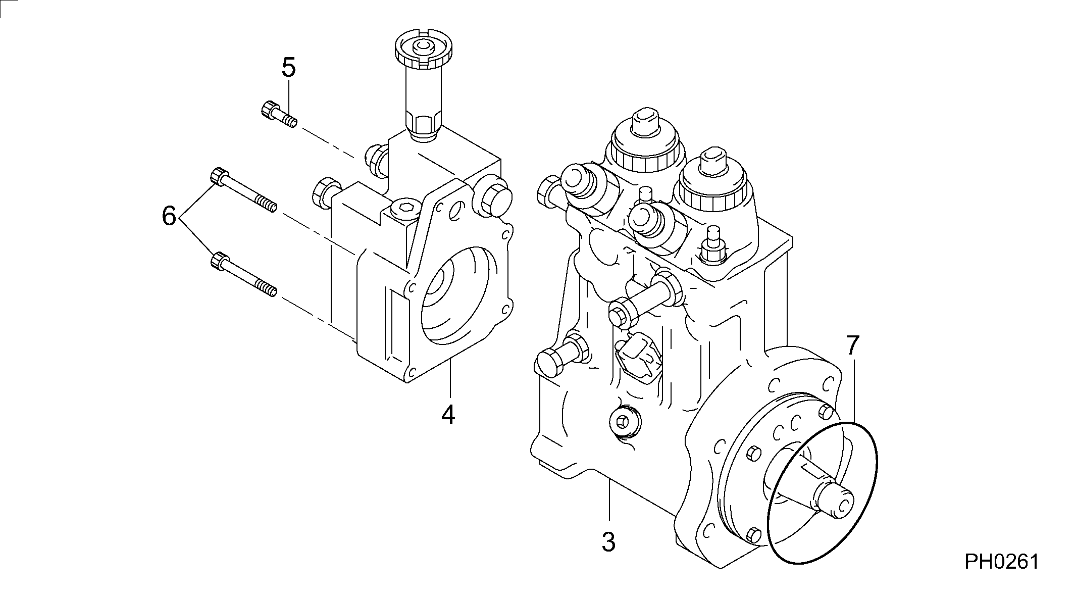
№
Qty
Part num
Name
Remarks
Manufacture num
000
[01]
09400-00710
PUMP ASSY, SUPPLY
CRS-HP0
Include in ##:
09400-00710
as PUMP ASSY, SUPPLY
Cross reference number
Part num
Firm num
Firm
Name
09400-00710
PUMP ASSY, SUPPLY
Information:
Start By:a. remove oil pumpb. remove oil pan plate 1. Remove No. 1, 3, 5 and 7 main bearing caps (1). Remove the lower halves of the main bearings from the main bearing caps.
If the crankshaft is turned in the wrong direction, the tab on the bearing will be pushed between the crankshaft and the bearing area in the cylinder block. This can result in damage to the cylinder block and/or the crankshaft.
2. Install Tool (A) in the hole in the crankshaft journal, and turn the crankshaft to remove the upper halves of main bearings (2).3. Remove crankshaft thrust bearings (3) from the rear main bearing. Install the main bearings dry when the clearance checks are made. Put clean engine oil on the main bearings for final assembly.
Make sure the upper and lower halves of the main bearings are installed so the bearing tabs fit into the notch in the cylinder block and the main bearing caps.
4. Use Tool (A), and install new upper halves of main bearings (2) in the cylinder block. Install new lower halves of main bearings (2) in main bearing caps (1).
When the bearing clearance is checked and the engine is in an upright position (vertical position with cylinder head on top), the crankshaft will have to be lifted up and held against the upper halves of the main bearings to get a correct measurement with the Plastigage. The Plastigage will not hold the weight of the crankshaft and give a correct indication. If the engine is in a horizontal position, it is not necessary to hold the crankshaft up. Do not turn the crankshaft when the Plastigage is in position to check clearances.
For complete details concerning measuring bearing clearances, see Engine Bearings And Crankshafts, Form No. SEBD0531.5. Check the main bearing clearance with Plastigage (B) as follows:a. Put a piece of Plastigage (B) on the crankshaft journals as shown.
Make sure the part number on the main bearing cap is toward the front of the engine and the number on the main bearing cap is the same as the number on the cylinder block on the left side of each main bearing cap.
b. Put main bearing caps (1) in position in the engine. Put 2P2506 Thread Lubricant on the bolt threads and the face of the washers. Install the bolts. Tighten the bolts to a torque of 40 4 N m (30 3 lb ft).c. Put a mark on each bolt and main bearing cap; then tighten the bolts 90° more.d. Remove the main bearing caps, and measure the Plastigage to find the bearing clearance. The main bearing clearance for new bearings must be 0.076 to 0.165 mm (.0030 to .0065 in.). Maximum permissible clearance with used bearings is 0.25 mm (.010 in.). 6. Put clean oil on the thrust bearing, and install a new thrust bearing for the rear main bearing. Install the thrust bearing with the identification "BLOCK SIDE" toward the cylinder block and the tabs on the thrust bearings