Rating:
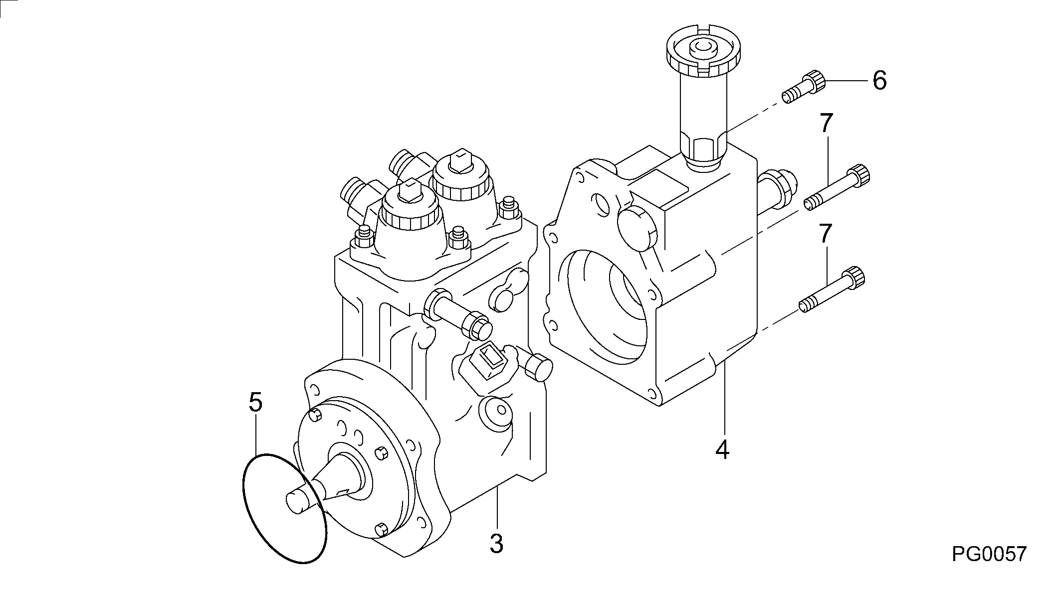
Information pump assy, supply Denso
Compare Prices: .
As an associate, we earn commssions on qualifying purchases through the links below

ZTUOAUMA CR HP0 Fuel Injection Pump 094000-0580 094000-0584 6261-71-1110 for Komatsu SAA6D140E Engine PC600-8 PC650-8 PC800-8 PC850-8 Excavator WA500-6 Wheel Loader HD325-7 HD405-7 Dump Truck
ZTUOAUMA Part Number: 094000-0580 094000-0584 6261-71-1110 || Application Models: Compatible with Komatsu SAA6D140 SAA6D140-E Engines || Compatible with Komatsu PC600-8 PC650-8 PC800-8 PC850-8 Excavator WA500-6 Wheel Loader HD325-7 HD405-7 Dump Truck || Direct Replacement; OEM Quality&Function; Easy Installation || All parts are strictly tested in factory to ensure the better function and durability
ZTUOAUMA Part Number: 094000-0580 094000-0584 6261-71-1110 || Application Models: Compatible with Komatsu SAA6D140 SAA6D140-E Engines || Compatible with Komatsu PC600-8 PC650-8 PC800-8 PC850-8 Excavator WA500-6 Wheel Loader HD325-7 HD405-7 Dump Truck || Direct Replacement; OEM Quality&Function; Easy Installation || All parts are strictly tested in factory to ensure the better function and durability

Fuel Injection Pump for Komatsu SAA6D140E-5 Engine PC650-8 PC600-8 PC800-8 WA500-6 Bulldozer HM350-2 HM400-2 Truck 094000-0584 6261-71-1111 6261-71-1112
KoovDem Part Number: 094000-0584, 0940000584, 6261-71-1111, 6261711111, 6261-71-1112, 6261711112 || Engine Model: for Komatsu SAA6D140E-5 Engine || Suitable Models: Compatible with Komatsu Excavator models PC650-8, PC600-8, PC800-8; Wheel Loader model WA500-6; Dump Truck models HM350-2 and HM400-2. || Effective and Reliable: Utilizing cutting-edge technology, this system delivers effective and reliable fuel supply, guaranteeing smooth vehicle performance. || Rugged and Dependable: With a track record of being rigorously tested and proven, this product offers durability and reliability, ensuring it operates consistently even in the harshest of environments.
KoovDem Part Number: 094000-0584, 0940000584, 6261-71-1111, 6261711111, 6261-71-1112, 6261711112 || Engine Model: for Komatsu SAA6D140E-5 Engine || Suitable Models: Compatible with Komatsu Excavator models PC650-8, PC600-8, PC800-8; Wheel Loader model WA500-6; Dump Truck models HM350-2 and HM400-2. || Effective and Reliable: Utilizing cutting-edge technology, this system delivers effective and reliable fuel supply, guaranteeing smooth vehicle performance. || Rugged and Dependable: With a track record of being rigorously tested and proven, this product offers durability and reliability, ensuring it operates consistently even in the harshest of environments.

IMELBUFF 094000-0584 6261-71-1111 HP0 Fuel Injection Pump for Komatsu SAA6D140E-5 Engine PC600-8 PC600LC-8 PC650LC-8E0 PC700LC-8 PC800-8 PC850-8 WA500-6 D275A-5 D155A-6 HD325-7 HM350-2 HM400-2
IMELBUFF 🚜Part Number: 094000-0584 6261-71-1111 || 🚜Engine Model: for Komatsu SAA6D140E-5 Series Engine || 🚜Vehicle Application: for Komatsu PC600-8 PC600LC-8 PC650LC-8E0 PC700LC-8 PC800-8 PC800LC-8 PC850-8 PC850-8E0 D275A-5 D155A-6 WA500-6 HD325-7 HD405-7 HM350-2 HM400-2 || 🚜Warm Tips: If you are not sure that the pump is suitable for your vehicle, please send us email with your vehicle engine model and fuel pump part number || 🚜Service: 6-months-warranty and 24 hour support for customer service. Please feel free to contact us by email if you have any question with the product
IMELBUFF 🚜Part Number: 094000-0584 6261-71-1111 || 🚜Engine Model: for Komatsu SAA6D140E-5 Series Engine || 🚜Vehicle Application: for Komatsu PC600-8 PC600LC-8 PC650LC-8E0 PC700LC-8 PC800-8 PC800LC-8 PC850-8 PC850-8E0 D275A-5 D155A-6 WA500-6 HD325-7 HD405-7 HM350-2 HM400-2 || 🚜Warm Tips: If you are not sure that the pump is suitable for your vehicle, please send us email with your vehicle engine model and fuel pump part number || 🚜Service: 6-months-warranty and 24 hour support for customer service. Please feel free to contact us by email if you have any question with the product
Include in ##:
Cross reference number
Part num
Firm num
Firm
Name
09400-00584
PUMP ASSY, SUPPLY
Information:
Start By:a. remove oil pumpb. remove oil pan plate 1. Turn the crankshaft until two pistons are at the bottom center. Remove connecting rod caps (1) from the two connecting rods. Remove the lower half of the rod bearing from the rod bearing cap.2. Push the connecting rods away from the crankshaft. Remove the upper half of the rod bearing from the connecting rod. Install the connecting rod bearings dry when the clearance checks are made. Put clean engine oil on the connecting rod bearings for final assembly.3. Install the upper half of the rod bearing in the connecting rod.4. Install the lower half of the rod bearing in the connecting rod cap. Be sure the tabs in the back of the connecting rod bearings are in the tab grooves of the connecting rod and cap. 5. Use Plastigage (A) to check the connecting rod bearing clearance.6. Put Plastigage (A) on the connecting rod bearing.7. Put 2P2506 Thread Lubricant on the threads of the rod bolts and seat surfaces of the nuts.
When connecting rod caps are installed, make sure the number on the side of the cap is next to and respective with the number on the side of the connecting rod.
Do not turn the crankshaft when Plastigage (A) is in position.
Do not use an impact wrench to tighten the nuts the additional 90°.
8. Install connecting rod cap (1). Install the nuts. Tighten the nuts to a torque of 40 4 N m (30 3 lb ft). Put a mark on each nut and the end of each bolt. Tighten the nuts 90° more. Remove the connecting rod caps. Remove Plastigage (A) and measure the width of the Plastigage. The connecting rod clearance must be 0.076 to 0.168 mm (.0030 to .0066 in) for new bearings. The maximum clearance with used bearings is 0.25 mm (.010 in).9. Install the connecting rod caps and tighten the nuts as in Step 8.10. Do Steps 1 through 9 for the remainder of the connecting rod bearings.End By:a. install oil pan plateb. install oil pump