Rating:
Information pump assy, injecti Denso
Product
Fuel Injection Pump
Vehicle engine
TRUCK 4D34T4
Engine
4D34T4
Serial start-end
Info
Injector Nozzle
093500-7500
Injector nozzle:
0935007500
KIT List:
Part name
Kit1
Kit2
Components :
Scheme #.#:
№
Qty
Part num
Name
Remarks
Manufacture num
000
[01]
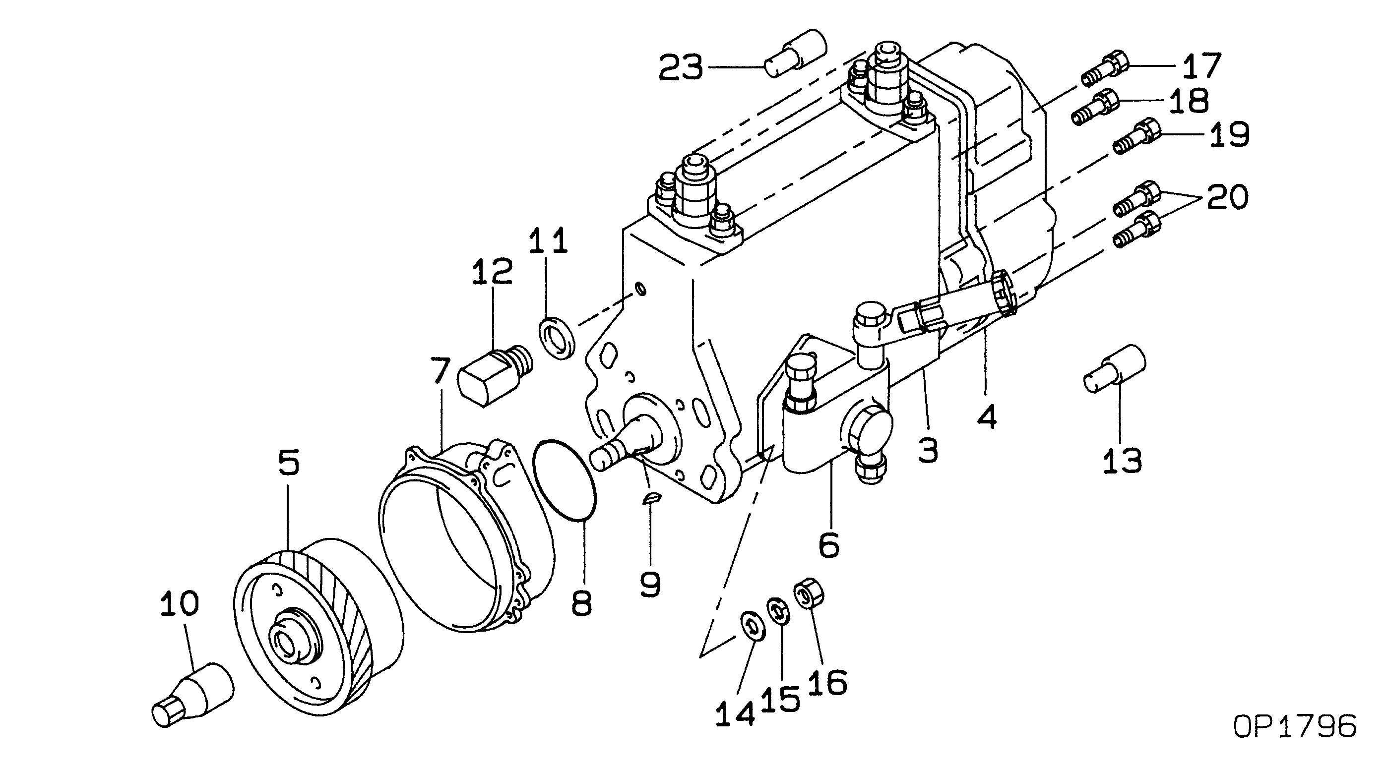
09300-07320
PUMP ASSY, INJECTI
NB4,R901
ME445393
MITSUBISHI
Include in ##:
09300-07320
as PUMP ASSY, INJECTI
Cross reference number
Part num
Firm num
Firm
Name
09300-07320
ME445393
PUMP ASSY, INJECTI
0930007320
ME445393
MITSUBISHI
PUMP ASSY, INJECTI
Information:
1. Use tool (A) to loosen the nuts on the fuel injection valves and use tool (B) to loosen the nuts on the adapter assemblies in the cylinder head. Remove inner fuel lines (1).
If necessary, use tooling (D) to turn the engine so the valves do not make contact with the pistons when the valves are opened with tool (C) to remove the push rods.
2. Put compression on the valve springs with tool (C) and remove push rods (2).3. Push the push rod end of the rocker arms down. 4. Remove the intake valve lifter with tooling (E) as follows: a) Install the 5P2685 Nut and the 5P6601 Collet on the 5P2408 Outer Handle Assembly.b) Install the 5P6599 Inner Handle Assembly in the 5P2408 Outer Handle Assembly.c) Install tooling (E) in the intake valve lifter. Hold the 5P2408 Outer Handle Assembly and tighten the 5P6599 Inner Handle Assembly until the 5P6601 Collet is tight against the inside of intake valve lifter. d) Remove intake valve lifters (3) from the cylinder block with tooling (E). 4. Remove the exhaust valve lifters with tooling (E) as follows: a) Install 5P2685 Nut (5) and 5P6601 Collet (6) on 5P2408 Outer Handle Assembly (4). The opening in the cylinder head for the intake valve lifter is larger than the opening in the exhaust valve lifter side. The tooling and each valve lifter