Rating:
Information pump assy, injecti Denso
Product
Fuel Injection Pump
Vehicle engine
TRUCK 4D34T7
Engine
4D34T7
Serial start-end
Info
Injector Nozzle
093500-7500
Injector nozzle:
0935007500
KIT List:
Part name
Kit1
Kit2
Components :
Scheme #.#:
№
Qty
Part num
Name
Remarks
Manufacture num
000
[01]
09300-07290
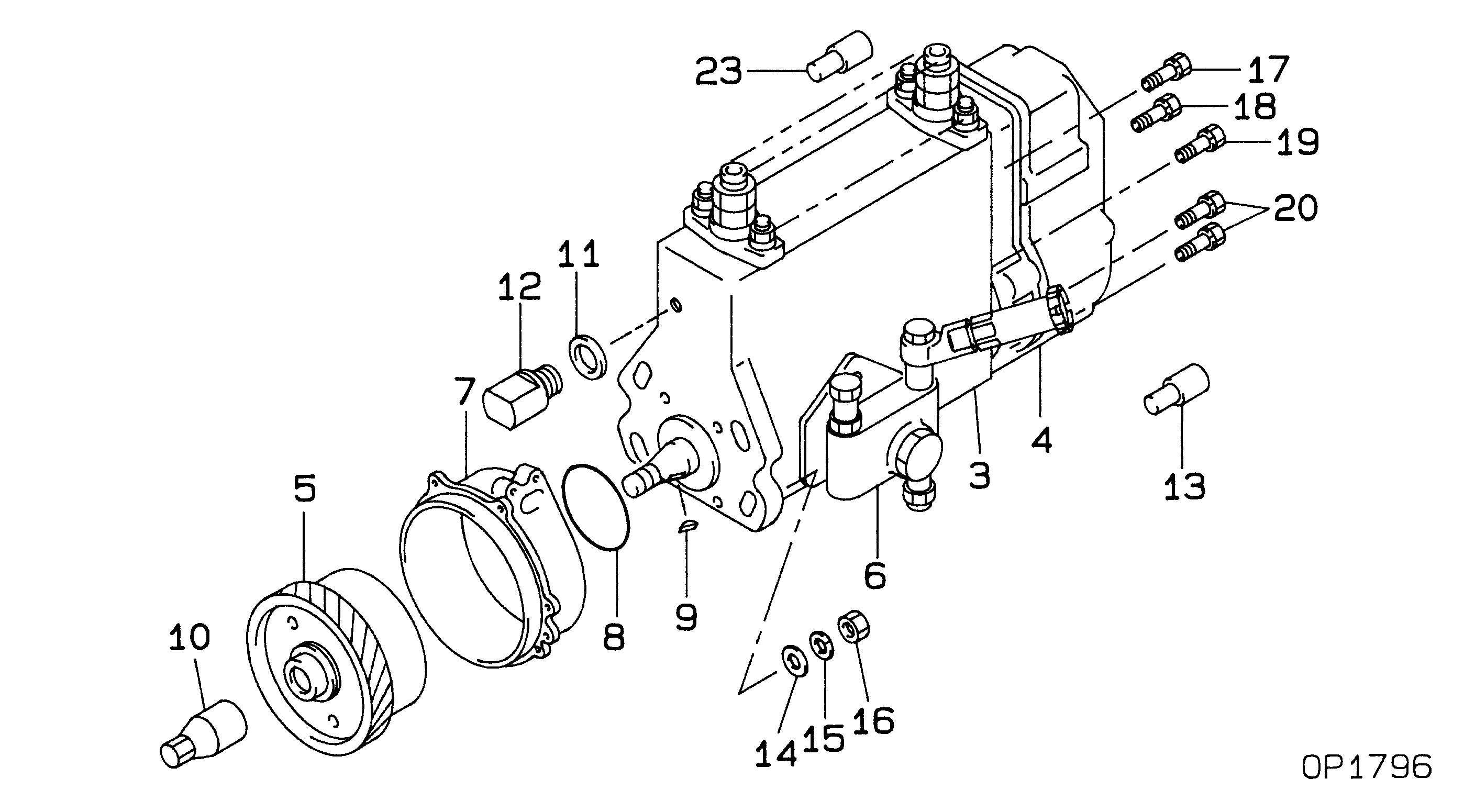
PUMP ASSY, INJECTI
NB4R901B
ME231082
MITSUBISHI
Include in ##:
09300-07290
as PUMP ASSY, INJECTI
Cross reference number
Part num
Firm num
Firm
Name
09300-07290
ME231082
PUMP ASSY, INJECTI
0930007290
ME231082
MITSUBISHI
PUMP ASSY, INJECTI

Information:
1. Remove four bolts (3) that hold elbow (1) to the inlet manifold. Remove elbow (1) and inlet pipe (2) as a unit. 2. Remove bolts (5) that hold the valve cover bases to the cylinder head. Remove valve cover bases (4). It will be necessary to disconnect the wire clips from the inner fuel injection lines for the precombustion chamber engines. 3. Remove inner fuel injection lines (6). Install caps and plugs on all injection line openings. 4. Remove bolts (7) that hold the rocker shafts to the cylinder head.5. Remove rocker shafts (8). 6. Remove push rods (9) from the valve lifters. 7. Remove bridges (10) from the dowels on the cylinder head.Install Rocker Shafts And Push Rods
1. Put clean engine oil on the bridges and dowels. 2. Install the bridges (1) on the dowels. Keep pressure by hand on the bridges and turn the adjustment screw clockwise until contact is made with the valve stem. Turn the screw an extra 20° to 30°. This will make dowel straight in guide and make compensation for gap (slack) in the threads. Hold adjustment screw in this position and tighten locknut to a torque of 22 3 lb.ft. (28 4 N m). 3. Install push rods (2). 4. Put rocker shafts (3) in position on the cylinder head.5. Put clean engine oil on the threads of the bolts that hold the rocker shafts in place. Tighten the bolts first to a torque of 200 20 lb.ft. (270 25 N m). Start with the bolt in the center of the rocker shaft. Tighten bolts again to a torque of 330 15 lb.ft. (450 20 N m). Tighten bolts again by hand to a torque of 330 15 lb.ft. (450 20 N m).
Do not cause damage to the O-ring seals on the inner fuel lines.
6. Install inner fuel injection lines (4). Tighten the fuel line nuts to a torque of 30 5 lb.ft. (40 7 N m) with tool (A) and (B). Connect wire clips to the fuel injection lines for the precombustion chamber engines.7. Make an adjustment to the valves to have a clearance of .015 in. (0.38 mm) for intake and .030 in. (0.76 mm) for the exhaust. Tighten the locknuts to a torque of 22 3 lb.ft. (28 4 N m) and check the valve clearance again. 8. Install valve cover bases (6) on the cylinder head. Install bolts (5) that hold the valve cover bases in place. Tighten the bolts to a torque of 120 24 lb.in. (13.6 2.8 N m). 9. Put clean oil on the O-ring seal on inlet pipe (8). Install inlet pipe (8) into the turbocharger. Make sure the gasket for elbow (7) is in position on the inlet manifold. Install four bolts that hold elbow (7) to the inlet manifold.end by:a) install valve covers