Rating:
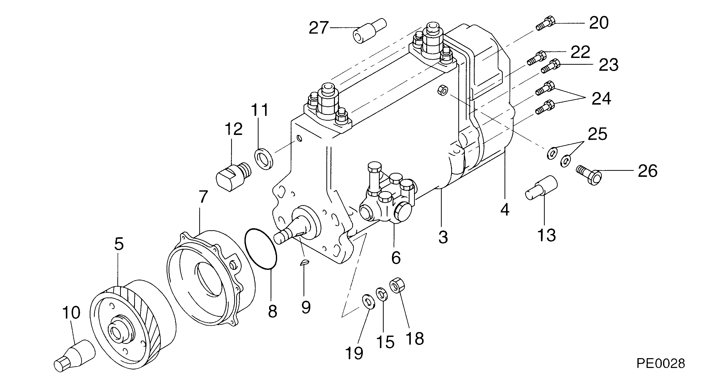
Information pump assy, injecti Denso
Components :
Scheme #.#:
№
Qty
Part num
Name
Remarks
Manufacture num
000
[01]
09300-06722
PUMP ASSY, INJECTI
NB4R901B
0601-
22010-E0110
HINO
Include in ##:
09300-06722
as PUMP ASSY, INJECTI
Cross reference number
Part num
Firm num
Firm
Name
09300-06722
22010-E011
PUMP ASSY, INJECTI
Information:
4. Remove the camshaft driveshaft cover at the top of the flywheel housing. Install a 3/8" - 16 NC forged eyebolt in the driveshaft (3) and remove the driveshaft. On engines with a BrakeSaver, remove two plugs (4) from the flywheel housing.5. Disconnect glow plug wiring harness from the glow plugs and valve cover base. Remove the inner fuel injection lines. Put plugs or caps on all fuel lines and openings. 6. Remove the fifteen other bolts and locks (seven each side and one in rear). Remove two of the glow plug wiring harness mounting bolts and install two 3/8" - 16 NC forged eyebolts. Pull the camshafts (5) off dowels. Fasten a hoist and remove the camshafts (5). Weight of the camshafts is 100 lb. (45 kg).Install Camshafts
1. Adjust all of the camshaft followers to give maximum clearance. 2. Put the camshaft phasing gear timing marks (1) together and in a horizontal plane. 3. Install two 3/8" - 16 forged eyebolts. Fasten a hoist and install the camshafts (2) on the engine. Install the camshaft retaining bolts and locks.
Never install the camshafts if the No. 1 piston is not at top center on the compression stroke. Damage to the engine can be the result if No. 1 piston is not in correct position.
4. Remove the eyebolts and install the glow plug wiring harness mounting bolts.5. Install the inner fuel injection lines. Tighten retaining nuts to 30 5 lb.ft. (40.7 6.8 N m).6. Connect the glow plug wiring to the plugs and to the valve cover base.7. Install the camshaft driveshaft with the alignment (blind) spline on top. Install driveshaft cover.8. Remove the timing bolt from the flywheel. Install the plug in the flywheel housing and timing bolt in the cover.9. Adjust the inlet valve clearance to .018 in. (0.46 mm) and the exhaust valve clearance to .030 in. (0.76 mm). 10. Install the valve cover (3) and the tube (4) from the turbocharger to the aftercooler.