Rating:
Information pump assy, injecti Denso
Product
Fuel Injection Pump
Vehicle engine
Construction machine 4M40
Engine
4M40
Serial start-end
0006-
Info
Injector Nozzle
093500-6900
Injector nozzle:
0935006900
KIT List:
Part name
Kit1
Kit2
Components :
Scheme #.#:
№
Qty
Part num
Name
Remarks
Manufacture num
Cross reference number
Part num
Firm num
Firm
Name
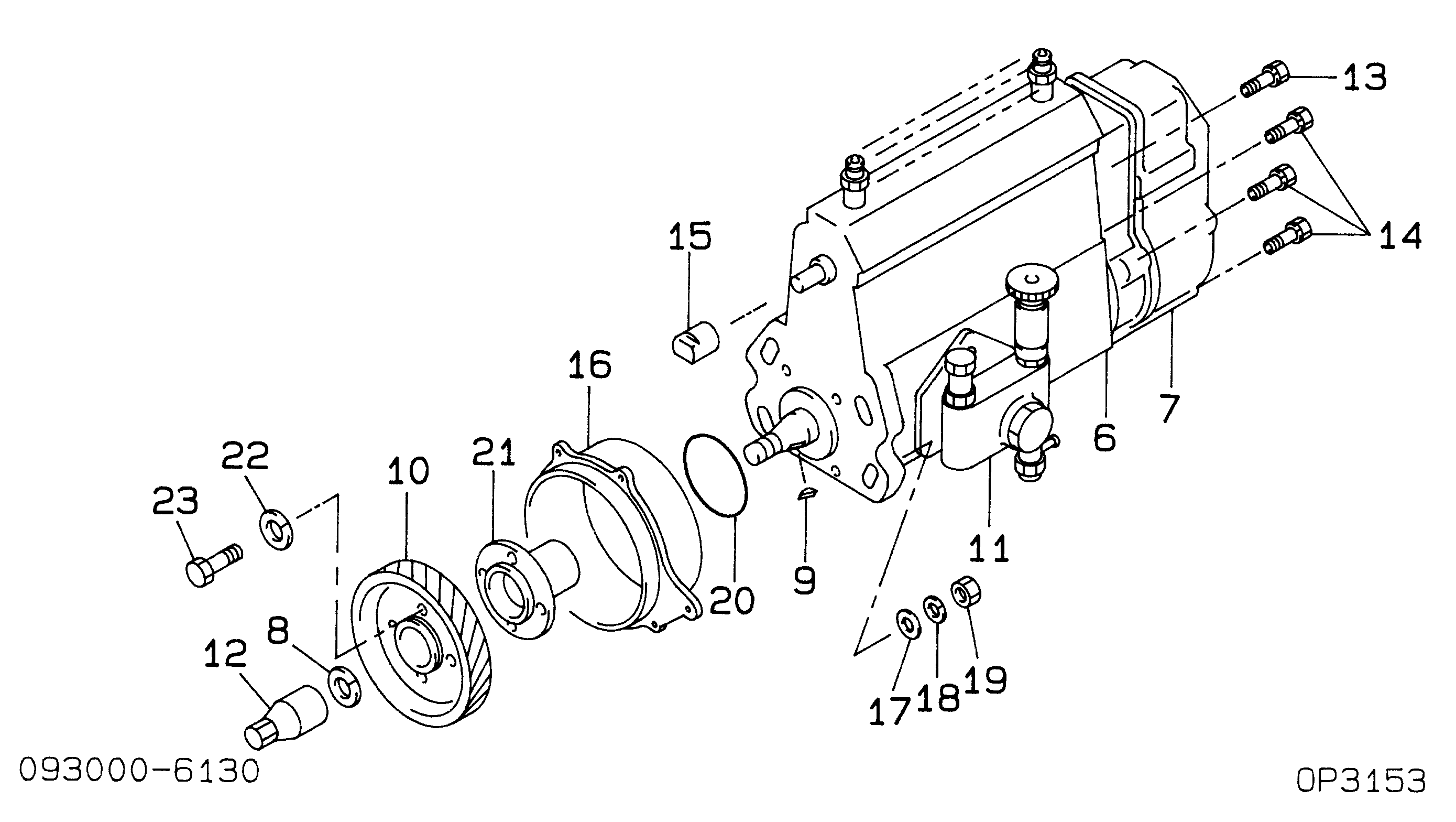
09300-06600
PUMP ASSY, INJECTI
Information:
Start By:a. remove cylinder headb. remove front and rear housingsc. remove rear seal and carrierd. remove pistons and connecting rods 1. Remove bolts (1), remove main bearing caps (2) and remove thrust bearings (3) from the center main. Caps are identified by numbers one through seven. Unmarked caps should be marked by stamping the appropriate number toward the right side of the bottom surface prior to removal. 2. Install two bolts and nylon strap (4) then carefully, remove the crankshaft. The approximate weight of the crankshaft is 129 kg (284 lb).3. Remove the upper portions of the main bearings. The following steps are for the installation of the crankshaft. Be sure main bearing tabs engage the grooves in the block and cap.4. Position the upper portion of the main bearings in the block and the lower main bearing portion in caps (2). Make sure everything is clean and only the bearing face is lubricated with engine oil.5. Position the crankshaft. 6. Install thrust bearings (3).7. Install main bearing caps (2) with the part numbers toward the right hand side of the cylinder block. Take care to insure the caps are numbered one through seven from the front of the engine. Put engine oil or molylube on the bolt threads and the washer face, then install bolts (1). Tighten the bolts on the side where the main bearing tabs are located to a torque of 95 5 N m (70 4 lb ft). Tighten the bolts on the opposite side to a torque of 95 5 N m (70 4 lb ft).8. Put a mark on each bolt head and the bearing caps. Turn the bolts that are opposite the main bearing tabs an additional 90° 5° turn. Then turn the bolts on the side where the main bearing tabs are located an additional 90° 5° turn.
Typical Example9. Use tooling (A) to measure crankshaft end play. The crankshaft end play must be 0.1 to 0.5 mm (.004 to .020 in).End By:a. install pistons and connecting rodsb. install rear seal and carrierc. install rear seal and carrierd. install cylinder head
Typical Example9. Use tooling (A) to measure crankshaft end play. The crankshaft end play must be 0.1 to 0.5 mm (.004 to .020 in).End By:a. install pistons and connecting rodsb. install rear seal and carrierc. install rear seal and carrierd. install cylinder head