Rating:
Information pump assy, injecti Denso
Components :
Scheme #.#:

№
Qty
Part num
Name
Remarks
Manufacture num
000
[01]
09300-05771
PUMP ASSY, INJECTI
A4,R801
ME215001
MITSUBISHI
Include in ##:
09300-05771
as PUMP ASSY, INJECTI
Cross reference number
Part num
Firm num
Firm
Name
09300-05771
ME215001
PUMP ASSY, INJECTI
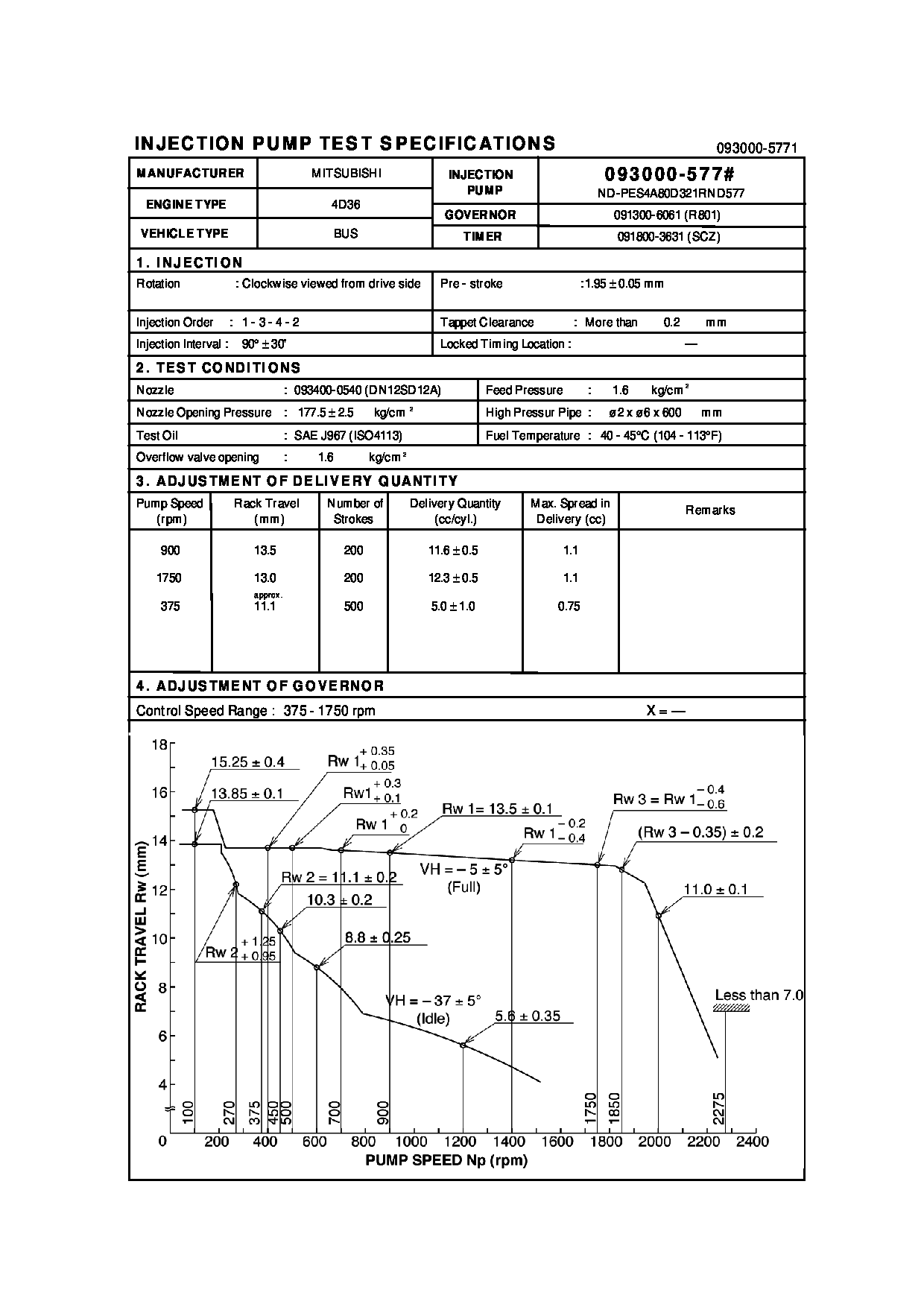
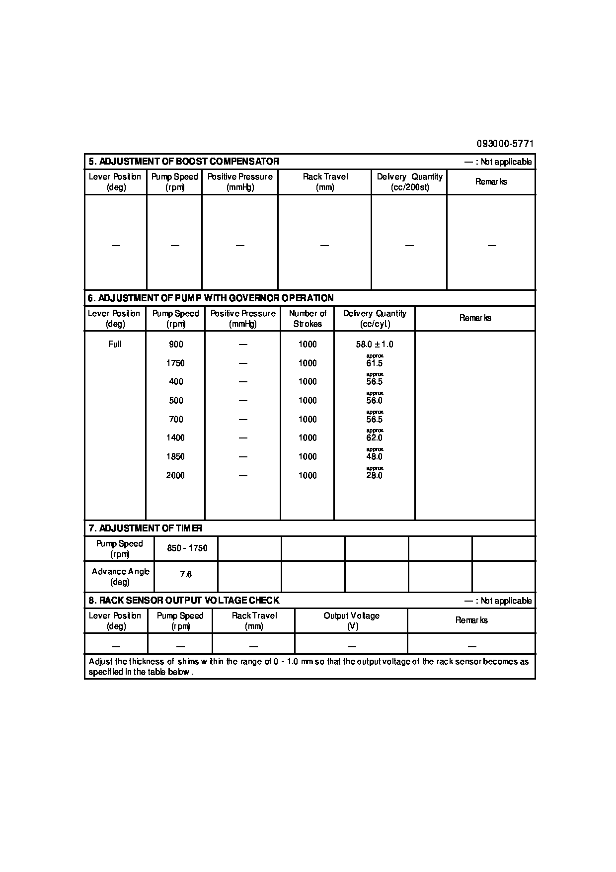
Test Calibration Data:
0930005770
ME215001
0930005771
ME215001
Information:
start by:a) remove oil pump1. Check the identification on the connecting rods and caps as to their location in the engine. The caps must be installed in original positions in the engine.2. Turn the crankshaft until two of the pistons are at bottom center. 3. Remove connecting rod caps (1) from the connecting rods. Remove the lower half of the bearings from the caps.
Be careful not to damage the crankshaft journals. Do not turn the crankshaft while any of the connecting rod caps are removed.
4. Push the connecting rod away from the crankshaft and remove the upper half of the bearings from the connecting rods.5. Make sure the surface of the connecting rod where the bearings make contact is clean and free of dirt.
Make sure the tabs on the bearings are in alignment with the notches in the connecting rods and caps.
6. Install the upper half of new bearings in the connecting rods.7. Pull the connecting rod down slowly on the crankshaft.
Make sure the surfaces where the bearings make contact in the caps are clean and free of dirt.
8. Install new bearings (2) in the caps. Make sure the tabs on the bearings are in alignment with the notches in the caps.9. Put clean engine oil on the threads of the bolts in the connecting rods.10. Check the bearing clearance with Plastigage (A) as follows: a) Make sure the numbers on the caps and connecting rods are the same and are on the same respective side. If new connecting rods are installed, put the cylinder number on the rods and caps.b) Put the caps and plastigage (A) in the correct position on the connecting rods. Install the nuts that hold them.c) Tighten the two nuts evenly to a torque of 60 6 lb.ft. (81.3 8.1 N m). Put a mark on each nut and tighten the nuts 120° more from the marks. d) Remove the caps from the connecting rods and Plastigage (A). Measure the thickness of the Plastigage. The connecting rod bearing clearance must be .0028 to .0066 in. (0.071 to 0.168 mm) for new bearings.e) Put clean engine oil in the bearing caps and install them again. Follow the tightening procedure in Step 10.f) Do Steps 1 through 10 for the other connecting rod bearings.end by:a) install oil pump