Rating:
Information pump assy, injecti Denso
Product
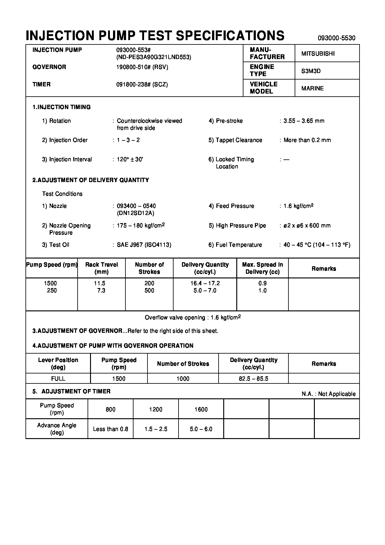
Fuel Injection Pump
Vehicle engine
MARINE S3M3D
Engine
S3M3D
Serial start-end
9601-
Info
Injector Nozzle
093500-4960
Injector nozzle:
0935004960
KIT List:
Part name
Kit1
Kit2
Components :
Scheme #.#:
№
Qty
Part num
Name
Remarks
Manufacture num
Cross reference number
Part num
Firm num
Firm
Name
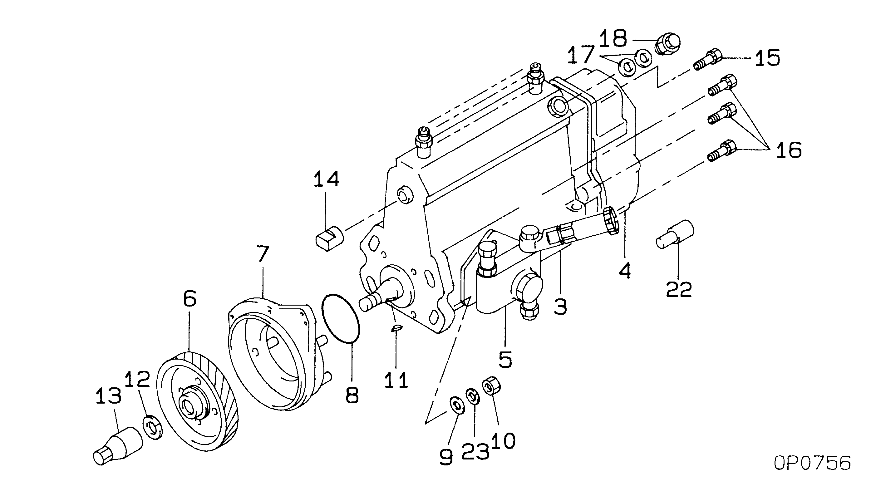
09300-05530
PUMP ASSY, INJECTI
Information:
1. Disconnect plug P8 from receptacle J8. The locking ring helps identify P8 from J8. Check the connections for damaged wires or pins and corrosion. Also check that the pins are at the proper height in the connector. Check that the wires and pins are tight in the connectors by pulling (slightly) on each wire of each connector (including the breakout "T").2. Install 8T8695 Adapter (nine pin breakout "T") between J8 and P8. Twist the locking rings to secure the connections.3. Connect the voltmeter as shown. Check for the appropriate voltages between the lettered "T" pins as explained in Steps 4 through 8.4. Pin A (+) to pin B (ground) system voltage should be approximately 12 volts DC with key on (no accessories). Minimum voltage is 11.0 volts DC. While cranking the voltage should be 8 to 12 volts DC. Diagnosis - Using the truck wiring schematic, check wires A and B and connections from J8 through the truck wiring harness back to the battery terminals for proper voltage.5. If the voltage check between pins A and B on P8 is less than 11.0 volts with the key on, check the voltage drop from pin B of the J8 connector to the negative battery post while cranking. For this test, the common lead (black) should be connected to the negative battery post first. Then place the positive (red) lead into pin B. (Pin B is chassis ground.) Voltage should be less than .5 volts DC when cranking. Diagnosis - If voltage drop is greater than .5 volts DC, check wire B and connections (including the battery post connections) from J8 to battery negative.6. Pin C to pin B: For best accuracy, a service tool [3176 (7X1055) DDT, or (8T8697) ECAP] should be used for this test to measure the pulse width modulated signal (see Electronic Troubleshooting, 3176 Diesel Truck Engine, Form No. SENR3913). If engine deceleration occurs too quickly (1.5 seconds or less), the retarder status cannot be accurately monitored by a service tool. Retarder status should then be monitored during a vehicle road test.* The throttle must be adjusted properly (must have less than 7% throttle at low idle).* All OEM wires and connectors to the retarder device must be connected.* With the cruise control off and truck in neutral, increase the engine speed to high idle by depressing the throttle pedal to maximum position.* Voltage should be 4 volts DC. Quickly release the throttle and allow the engine to return to the low idle position.* During the engine deceleration from high idle to 950 rpm, voltage should be approximately 1 volt DC. (Do not depress the clutch pedal during this procedure.) Diagnosis - Check the retarder enable circuit, using the truck wiring schematic, from Pin C (P8) to the retarder device (Jake brake or exhaust brake).7. Pin F to Pin B:(Equipment supplied with the engine monitoring option module).* 1 to 4 volts DC with the key on and warning buzzer on (warning buzzer sounds for first