Rating:
Information pump assy, injecti Denso
Product
Fuel Injection Pump
Vehicle engine
TRUCK 4D36
Engine
4D36
Serial start-end
9503-
Info
Injector Nozzle
093500-5940
Injector nozzle:
0935005940
KIT List:
Part name
Kit1
Kit2
Components :
Scheme #.#:
№
Qty
Part num
Name
Remarks
Manufacture num
Cross reference number
Part num
Firm num
Firm
Name
09300-05280
PUMP ASSY, INJECTI
0930005280
ME012939
MITSUBISHI
PUMP ASSY, INJECTI
Information:
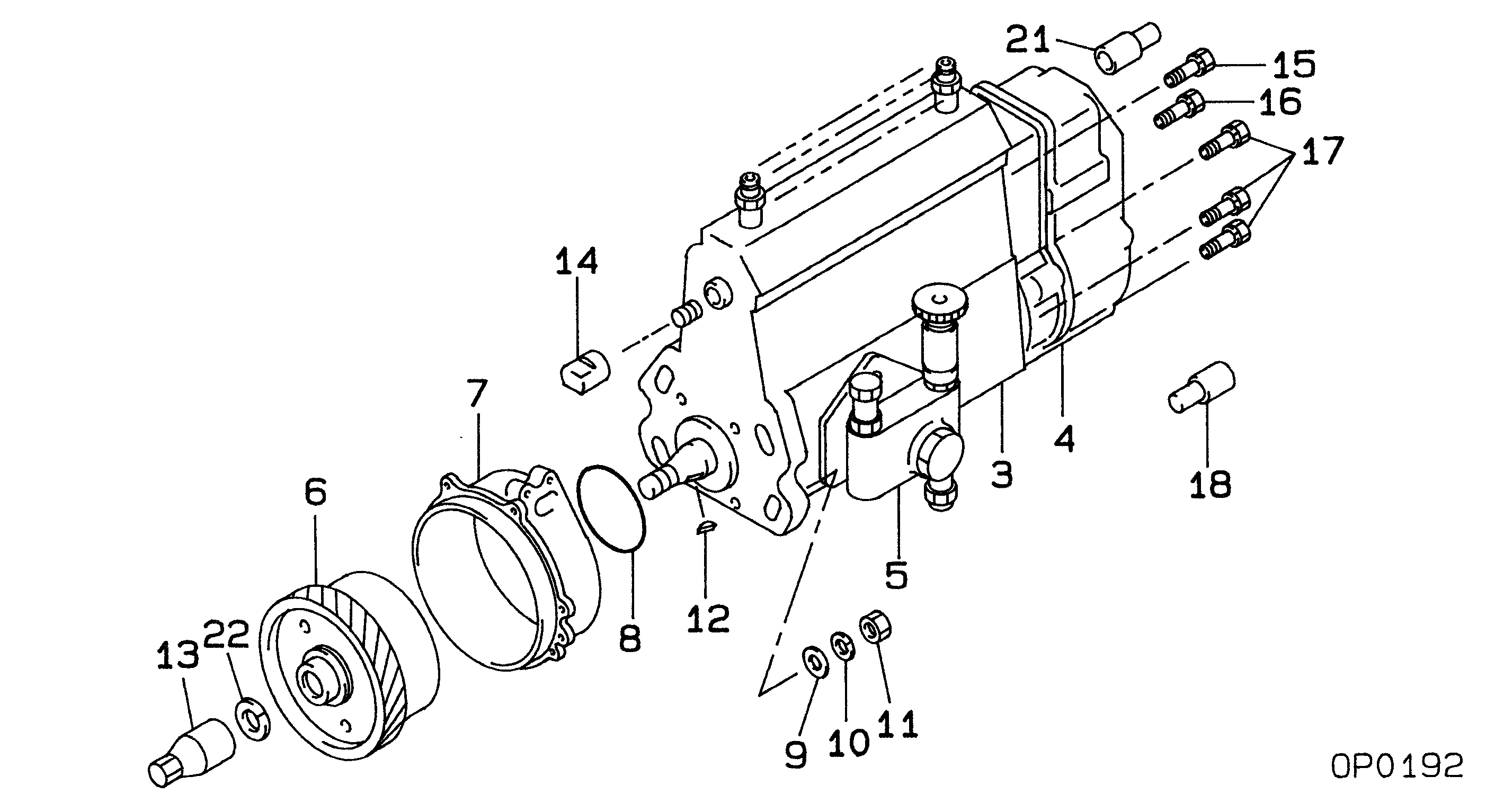
1. Remove two bolts (1) and remove oil supply line (2). Remove two bolts (3), loosen hose clamp (4) and move drain tube (5) out of the way. 2. Remove four nuts (6). Remove the turbocharger. The following steps are for the installation of the turbocharger.3. Apply 5P3931 Anti-Seize to turbocharger mounting studs. Position turbocharger gasket and turbocharger. Install four nuts (6). Tighten nuts to a torque of 55 5 N m (40 4 lb ft).4. Position drain tube with gasket and install bolts (3), then tighten hose clamp (4). Position oil supply line (2) with gasket and install bolts (1).Disassemble & Assemble Turbocharger
Start By:a. remove turbocharger 1. Place turbocharger in tooling (A). Put alignment marks on all the housings. Loosen clamp (1) and remove housing (2). 2. Loosen clamp (3) and remove cartridge assembly (4). 3. Place cartridge assembly (4) in tooling (B).
Use a 5S9566 Sliding T-Wrench and a universal socket to remove nut (5). Do not bend or add stress to the shaft when nut (5) is loosened or tightened.
4. Remove nut (5) and remove compressor wheel (6).5. Remove snap ring (7), then use two screw drivers and remove adapter plate (8). Remove O-ring seal (9) and inspect.6. Remove and inspect bushing and seal (10).7. Remove oil deflector (11) and thrust ring (12).8. Remove bearing (13), sleeve (14) and thrust ring (15).9. Lift housing assembly (19) off of shaft and wheel (20).10. Use snap ring pliers and remove wrap around snap ring (16), then remove double bushing (17).11. Remove seal ring (21) and backplate (18).12. Check all parts of the turbocharger for damage. If any parts are damaged, use new parts for replacement. See Special Instructions Form No. SMHS6854 for turbocharger reconditioning. Also, see Guidelines For Reusable Parts, Form No. SEBF8018. The following steps are for the assembly of the turbocharger.13. Make sure that all the oil passages in the turbocharger cartridge housing are clean and free of dirt and foreign material. Do not put oil on any parts of the turbocharger until after the compressor wheel has been assembled, put clean engine oil into the oil inlet of the turbocharger.14. With shaft and wheel (20) in tooling (B), install seal (21).15. Install double bushing (17) into housing (19) and install wrap around snap ring (16). Position housing assembly (19) onto shaft and wheel (20).16. Install thrust ring (15), bearing (13), sleeve (14) and thrust ring (12). Install oil deflector (11) then bushing and seal (10).17. With oil seal (9) in place, position adapter plate (8) and install snap ring (7).
Do not bend or add stress to the shaft when nut (5) is tightened.
18. Install compressor wheel (6) on the shaft. Put one drop of 9S2365 Retaining Compound on the threads of the shaft. Install nut (5) and torque it to 14.4 0.5 N m (144 5 lb in).19. Remove cartridge assembly (4) from tooling (B) and install it into the housing on tooling (A). Align marks and tighten clamp (3).20. Install