Rating:
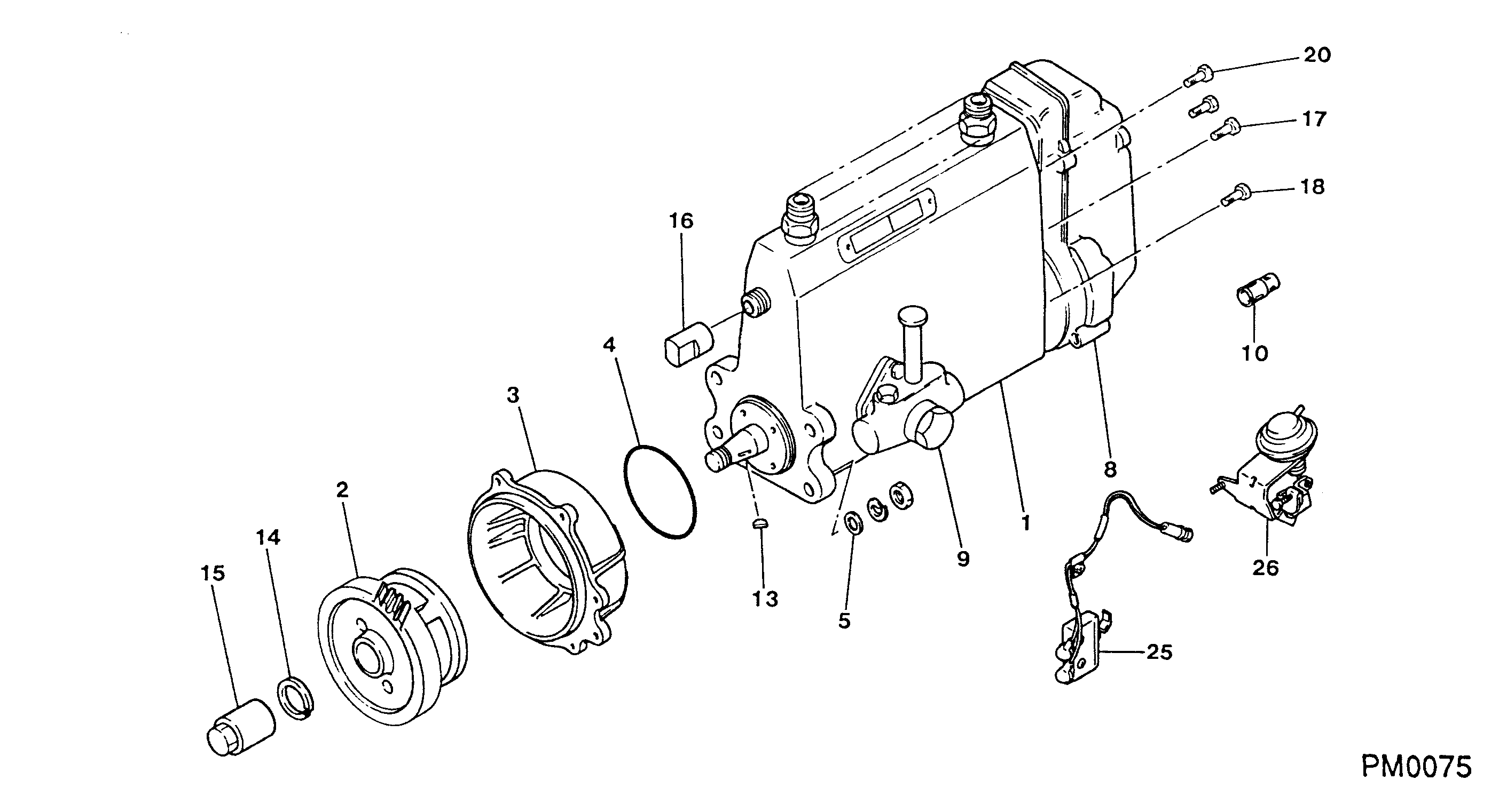
Information pump assy, injecti Denso
Components :
Scheme #.#:
№
Qty
Part num
Name
Remarks
Manufacture num
000
[01]
09300-02194
PUMP ASSY, INJECTI
A4,R801
9309-
ME016413
MITSUBISHI
Include in ##:
09300-02194
as PUMP ASSY, INJECTI
Cross reference number
Part num
Firm num
Firm
Name
09300-02194
ME016413
PUMP ASSY, INJECTI
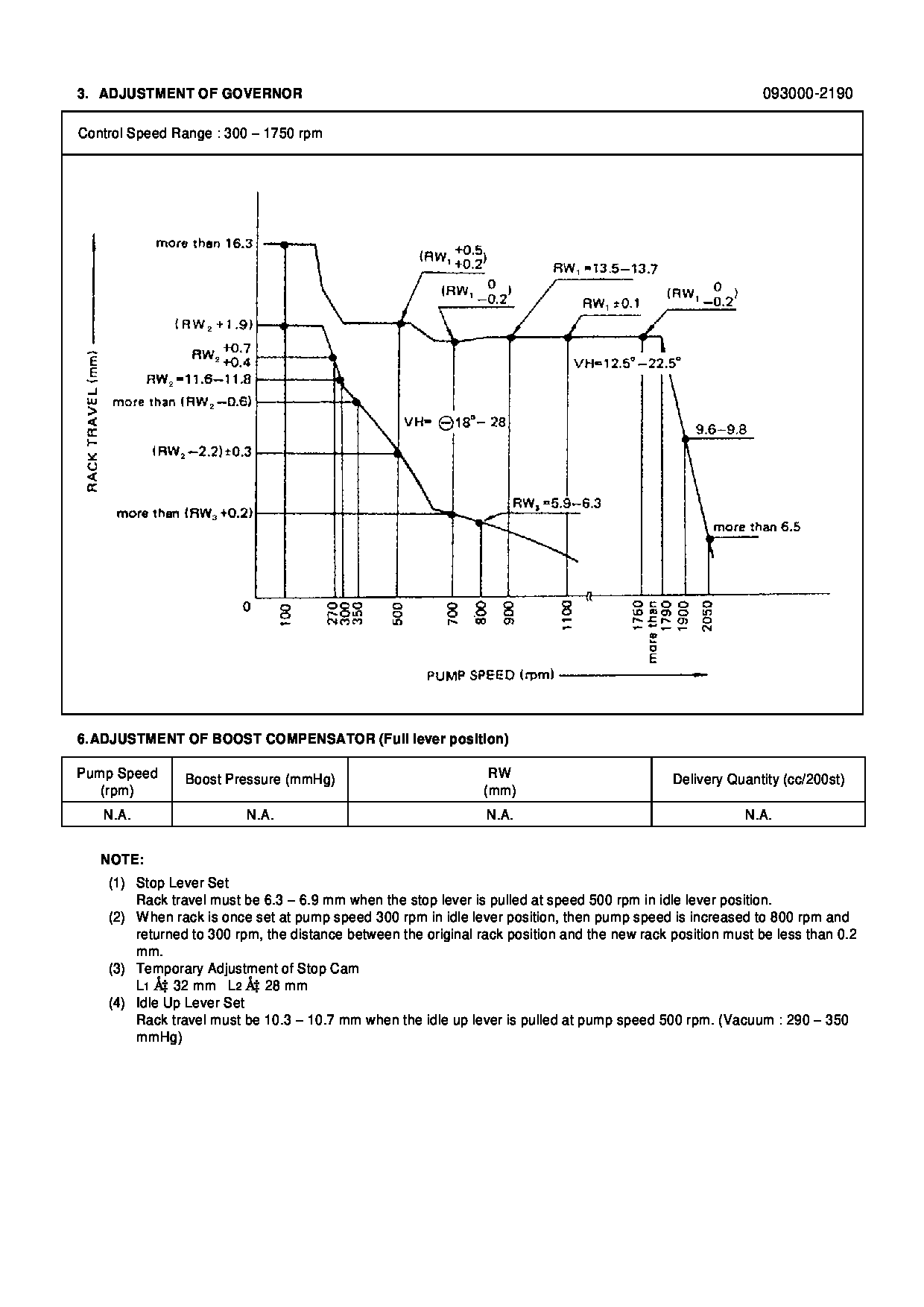
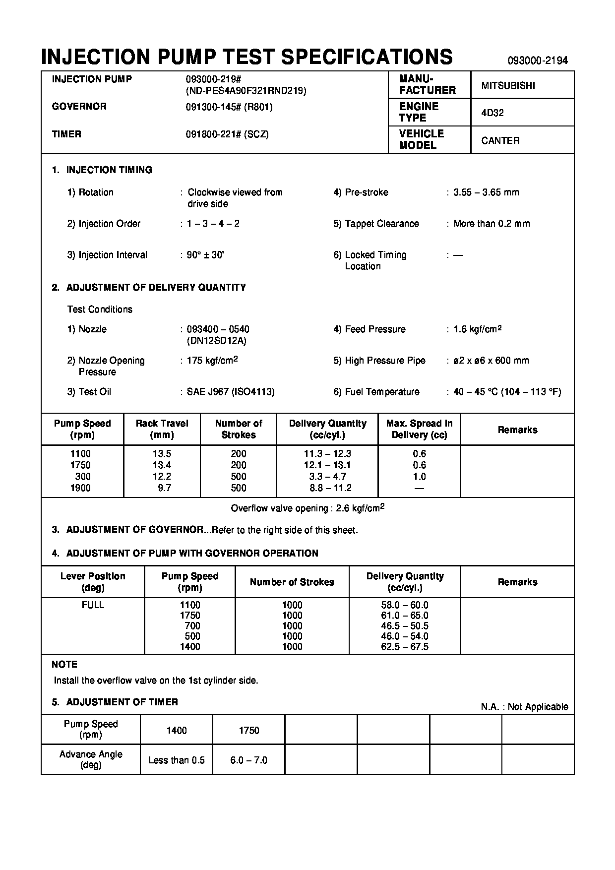
Test Calibration Data:
0930002190
ME016413

0930002194

Information:
Introduction
This Special Instruction provides detailed instructions on the installation of the sleeve into the compensator group of the 3408E and 3412E Unit Injector Hydraulic Pump. If leaks are experienced at the joint of the compensator and the adapter block, the 174-8943 Sleeve may be installed to improve sealing. The new press fit sleeve contains the O-ring more securely than the original slip fit sleeve.Note: Engines built prior to the serial number break that contain the new sleeve have a "S" stamped at the end of the part number on the serial number plate of the pump. The reworked part numbers appear as "144-0835-06S". Individual Components
Table 1
Quantity Part Number Part Description
1 174-8943 Sleeve
1 135-2652 O-Ring
1 033-6039 O-Ring
6 9X-7680 O-Ring Necessary Tools
One of the following tools may be used to insert the new sleeve into the compensator group.
A 31.750 mm (1.250 inch) diameter flat plate.
The 1P-0467 Drive Plate from 1P-0510 Driver Group .
An acceptable bearing insertion tool.Removal Of The O-Ring Seals
Illustration 1 g00638376
Remove the four bolts (1) from the compensator (2). Remove the compensator and the adapter. Do not adjust the compensator. Refer to Special Instruction, REHS0192-03, step 3 of procedure for "Disassembly of the 144-0835 Unit Injector Hydraulic Pump Group ".
Illustration 2 g00638368
Remove the four O-ring seals (3) from the bottom side of the adapter. Refer to Special Instruction, REHS0192-03, step 4 of procedure for "Disassembly of the 144-0835 Unit Injector Hydraulic Pump Group ".
Illustration 3 g00638372
Remove the four O-ring seals (4) from the two housings. Refer to Special Instruction, REHS0192-03, step 5 of procedure for "Disassembly of the 144-0835 Unit Injector Hydraulic Pump Group ".
Remove the slip fit sleeve from the compensator housing.Installation Of The Sleeve
Illustration 4 g00637918
(1) Compensator assembly. (2) 174-8943 Sleeve .
Invert the compensator assembly (1). Hold the compensator assembly securely within a vise or a press table.
Start the sleeve (2) by hand into the compensator assembly (1) .Note: It is important that the groove on the outside diameter of the sleeve is oriented toward the O-ring in the joint. If this is not done, there will not be sufficient room to properly seal the O-ring.
Press the sleeve (2) flush with the surface of the compensator assembly (1) using the 1P-0467 Drive Plate or by using an acceptable bearing insertion tool.Installation Of The O-Ring Seals
Illustration 5 g00638368
Install the four O-ring seals (3) on the bottom side of the adapter. Refer to Special Instruction, REHS0192-03, step 16 of procedure for "Assembly of the 144-0835 Unit Injector Hydraulic Pump Group ".
Illustration 6 g00638372
Install the four O-rings (4) on the two housings. Refer to Special Instruction, REHS0192-03, step 17 of procedure for "Assembly of the 144-0835 Unit Injector Hydraulic Pump Group ".
Illustration 7 g00638376
Install the compensator assembly (2) and the adapter as a unit vertically so that the O-rings seals are not damaged. Tighten the four bolts (1) to the following torque.Torque for bolts ... 8 1 N