Rating:
Information pump assy, injecti Denso
Components :
Scheme #.#:
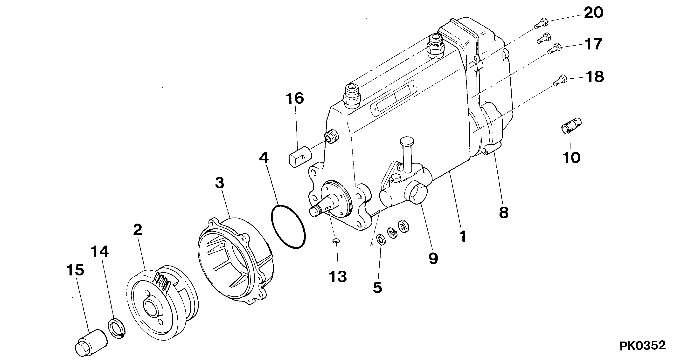
№
Qty
Part num
Name
Remarks
Manufacture num
000
[01]
09300-02133
PUMP ASSY, INJECTI
A4,R801
9309-
ME016405
MITSUBISHI
Include in ##:
09300-02133
as PUMP ASSY, INJECTI
Cross reference number
Part num
Firm num
Firm
Name
09300-02133
ME016405
PUMP ASSY, INJECTI
Test Calibration Data:
0930002130
ME016405
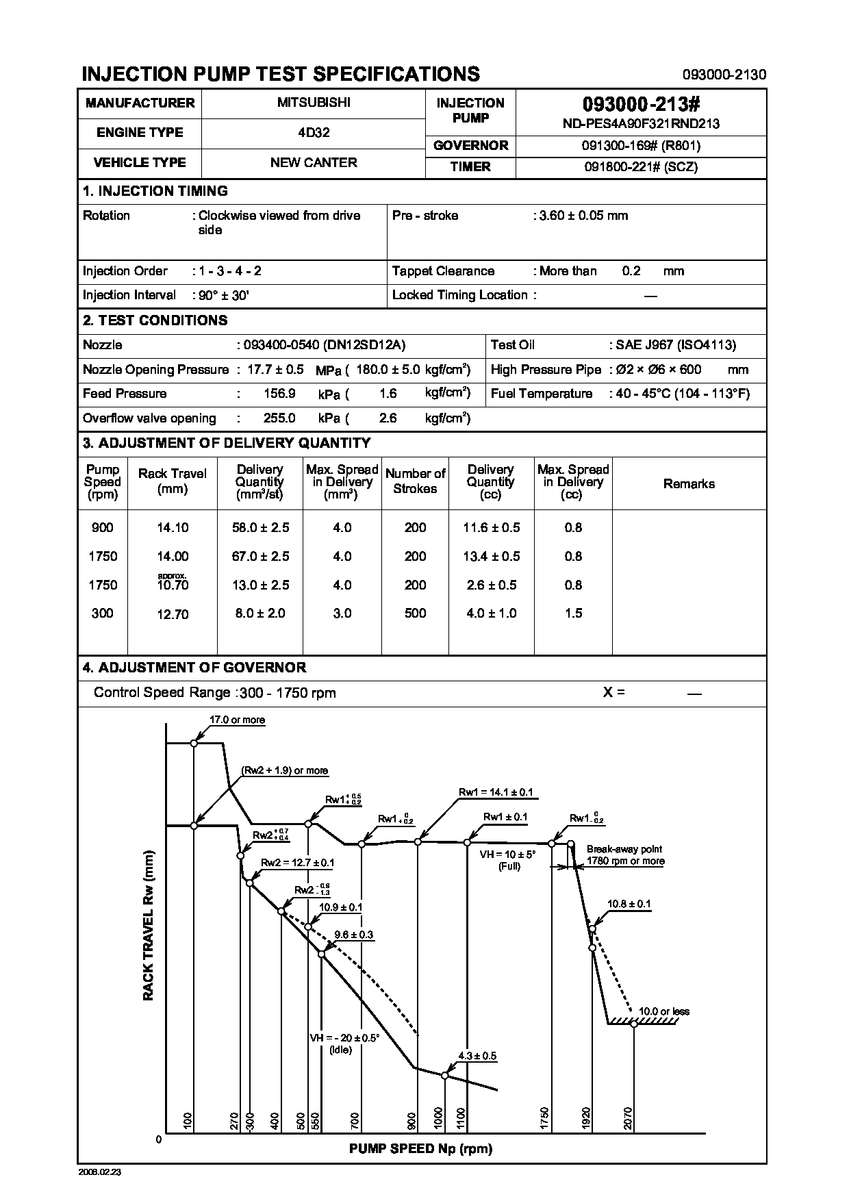
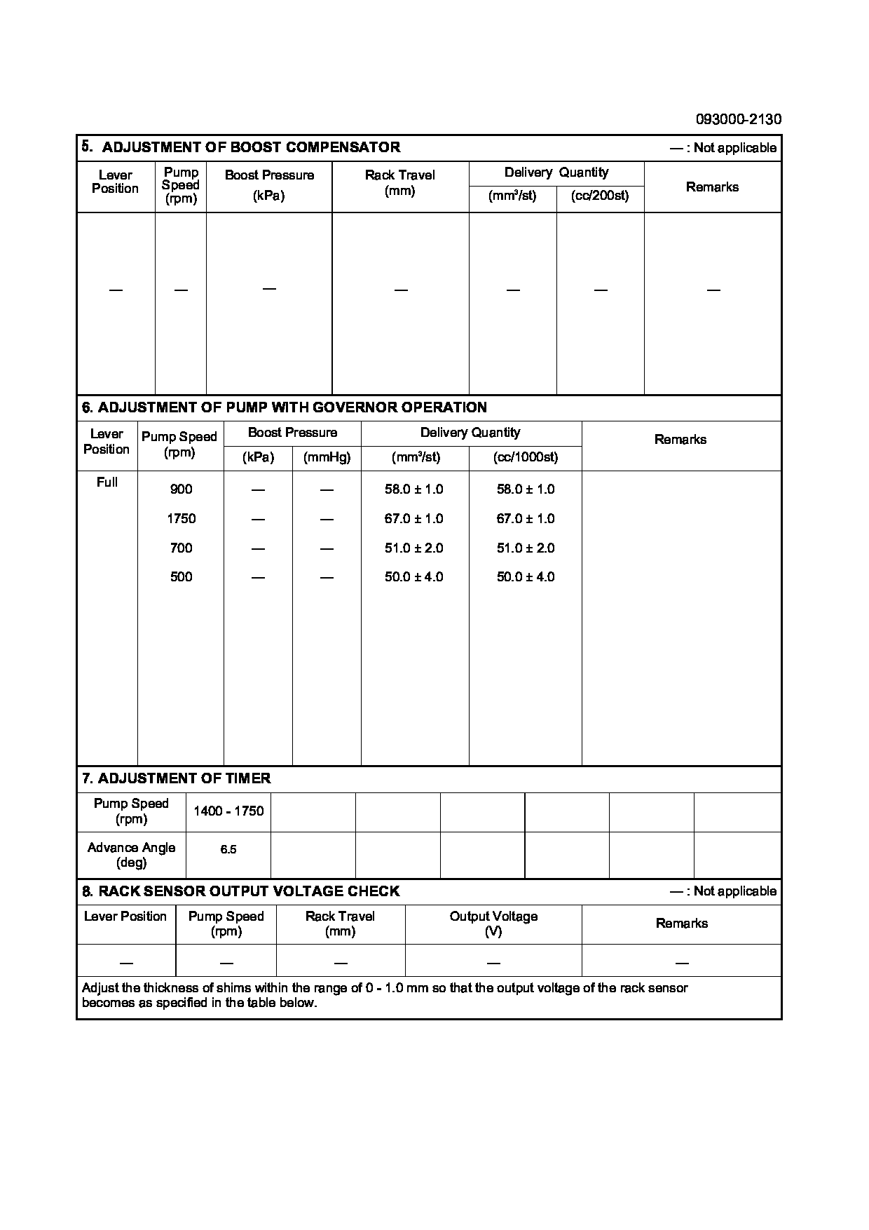
0930002131
ME016405
0930002132
ME016405
0930002133
ME016405
Information:
Introduction
There have been isolated occurrences of excessive fuel leakage past the electronic unit injectors on some engines.Accelerated wear on the delivery valve results in an increased leak rate.For six cylinder engines, the fuel injection pump cannot generate enough fuel flow or volume to compensate for the leak-off rates above a critical value of 38 mL (1.3 oz) per 30 seconds of cranking at a speed of 150 rpm.For four cylinder engines, the critical value is 25 mL (0.85 oz) per 30 seconds of cranking at a speed of 150 rpm.If the engine turns over but the engine does not start, refer to Troubleshooting, "Engine Cranks but Will Not Start". Perform the following procedure when directed by Troubleshooting, "Engine Cranks but Will Not Start". The procedure will help to assess the amount of fuel pressure leak-off within the high-pressure fuel system.Note: The engine may start, but you may still have high leak-off within the high-pressure fuel system.
Do not perform any procedure in this Special Instruction until you read this information and you understand this information.
Note: If the electronic unit injectors are replaced, ensure that the valve bridge is seated in the correct position. Failure to carry out this procedure correctly may result in engine failure. For further information, refer to Engine News, SEBD9574, "Improved Valve Bridges" and Service Magazine, SEPD0975, "Improved Valve Bridges".Note: If applicable, a completed service report (form number 089479-00) must be included with the returned parts. ECM warranty report downloads, datalogs, and any special test results as directed by repair procedures are to be uploaded to SIMS. Checklists that are packaged with replacement parts are to be completed and packaged with parts being returned.Refer to Special Instruction, REHS7790, "Improved Fuel System Diagnostic Test Documentation for Certain C4.4 and C6.6 Engines" for additional diagnostic test documentation.Test Procedure for Measuring High Leak-off for the Electronic Unit Injectors
Before beginning any work on the fuel system, refer to Operation and Maintenance Manual, "General Hazard Information and High-Pressure Fuel Lines" for safety information.Refer to Systems Operation, Testing and Adjusting, "Cleanliness of Fuel System Components" for cleanliness information on the fuel system.
Note: Caterpillar recommends that the procedure should be carried out without starting the engine.
Table 1
Required Tools
Tool Part Number Part Description Qty
A 300-4988 Fuel Leakoff Kit 1
Ensure that the engine is shut down. Remove the banjo bolt that is on the bottom of the fuel transfer pump.
Illustration 1 g01402111
Typical example
Install Tooling (A) to the fuel transfer pump.Note: Tooling (A) will replace the banjo bolt that was removed in Step 1. Do not substitute Tooling (A). Tooling (A) is specially designed for the test.
Install a clear plastic hose (1). Place the opposite end of the plastic hose into a suitable container that is clean.
Connect the electronic service tool to the diagnostic connector.
Disconnect the three harness connectors for the electronic unit injectors at the valve mechanism cover base to prevent starting the engine.
Perform a data log of the following parameters at a sample rate of 240 samples per minute.ECM Parameters
Active Diagnostic Codes that are