Rating:
Information pump assy, injecti Denso
Components :
Scheme #.#:
№
Qty
Part num
Name
Remarks
Manufacture num
000
[01]
09300-02084
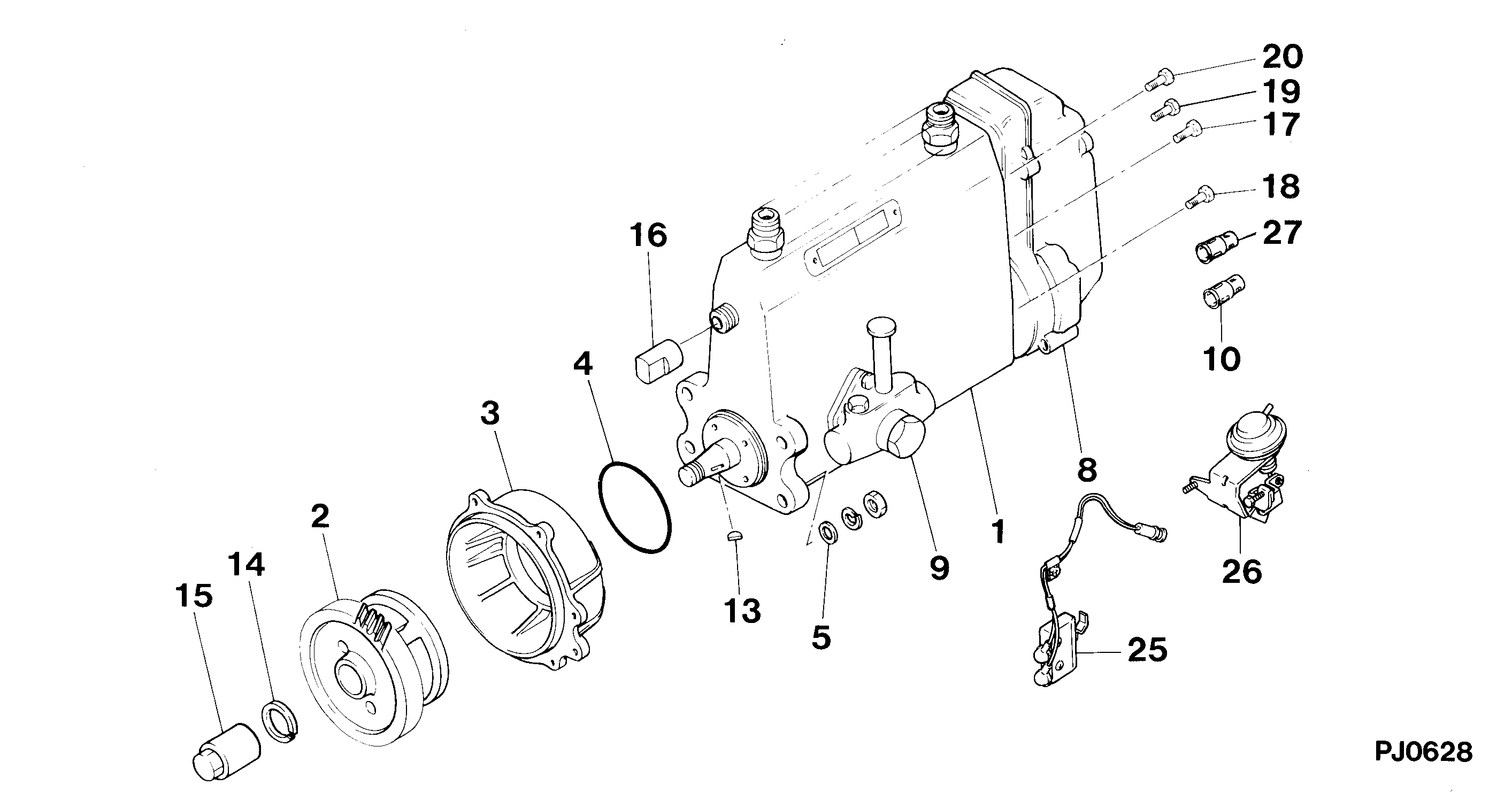
PUMP ASSY, INJECTI
A4,R801
9309-
ME016268
MITSUBISHI
Include in ##:
09300-02084
as PUMP ASSY, INJECTI
Cross reference number
Part num
Firm num
Firm
Name
09300-02084
ME016268
PUMP ASSY, INJECTI
Test Calibration Data:
0930002080
ME016268
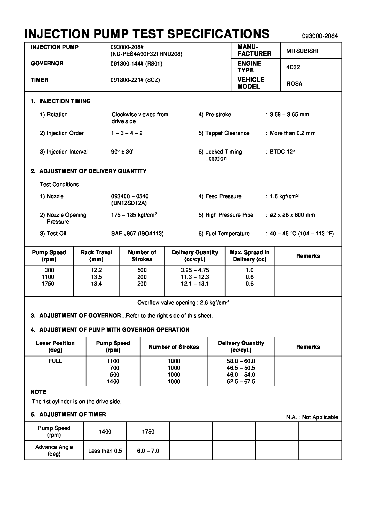
0930002084
Information:
Illustration 1 g00566932
ETR Junction Box with oil pressure protection (OP), water temperature protection (WT), and overspeed protection (OS) that requires a switchgear for use on 3200 through 3400 Engines
(1) Terminal strips (TS)
(2) Wiring harness
(3) Electronic speed switch (ESS)
(4) Junction box
(5) Identification foil
(6) Jumper between terminals (TS-3) and (TS-4)
(7) Diodes (D3) and (D4)
(8) Emergency stop switch (ES)
(9) Jumper between terminals (TS-27) and (TS-28)
(10) Jumper between terminals (TS-28) and (TS-29)
(11) Slave relay (SR1)
(12) Slave relay (SR2)
(13) Grommets for engine oil pressure switches
(14) Wiring harness connections for switchgear
(15) Circuit breakers
(16) Engine oil pressure switch (OPS1)
(17) Mounting brackets for grommets
Illustration 2 g00290526
ETR Junction Box with oil pressure protection (OP), water temperature protection (WT), and overspeed protection (OS) that requires a switchgear for use on3500 Engines
(1) Terminal strips (TS)
(2) Wiring harness
(3) Electronic speed switch (ESS)
(4) Junction box
(5) Identification foil
(6) Jumper between terminals (TS-3) and (TS-4)
(7) Diodes (D3) and (D4)
(8) Emergency stop switch (ES)
(9) Jumper between terminals (TS-27) and (TS-28)
(10) Jumper between terminals (TS-28) and (TS-29)
(11) Jumper between terminals (TS-30) and (TS-31)
(12) Diode for electric governor actuator (if equipped)
(13) Slave relay (SR1)
(14) Slave relay (SR2) for air shutoff solenoid (ASOS)
(15) Slave relay (SR3) for starting aid switch
(16) Grommets for engine oil pressure switches
(17) Wiring harness connections for switchgear
(18) Circuit breakers
(19) Engine oil pressure switch (OPS1)
(20) Mounting bracket for grommets
(21) Engine oil pressure switch (OPS2) (if equipped) Introduction
The ETR Junction Box with oil pressure protection (OP), water temperature protection (WT), and overspeed protection (OS) that requires a switchgear is a system that has full protection. The switchgear must be provided by the customer. After the customer's switchgear is wired into the junction box, the electric protection system becomes functional. The system has a junction box arrangement that is designed to monitor four functions:
Engine overspeed
Crank termination
Oil pressure
Coolant temperatureThe junction box includes the following components:
Electronic speed switch (ESS) (3)
Slave relay (SR1) (11) and (13)
Slave relay (SR2) (if equipped) with an air shutoff solenoid (ASOS) (12) and (14)
Oil pressure switch (OPS1) (16) and (19)
Oil pressure switch (OPS2) that is only in 3500 Engines (21)
Emergency stop switch (ES) (8)The components that are listed below operate with the junction box. The components are also mounted on the engine.
Fuel shutoff solenoid (FSOS)
Air shutoff solenoid (ASOS)
Water temperature switch (WTS)The slave relay (SR1) must be energized in order for the engine to run with the ETR electric protection system.Electrical Schematic And Wiring Diagrams
This manual contains the point-to-point wiring diagrams for the complete electric protection system and the junction box. Four types of electrical schematics for each electric protection system arrangement are shown in this service manual.
Junction box wiring diagram
IEC (International Electro-Technical Commission) schematic
JIC (Joint Industrial Council) schematic
Junction box wiring harness diagramNote: The line number that follows a component code gives the location of the component on the IEC and JIC schematics.Circuit Operation With No Faults
The steps that follow use a start/stop switch with three positions in order to interface with the switchgear that is supplied by the customer. Connect the contacts of the switch to the terminal strip in the junction box.
Connect the contacts for