Rating:
Information pump assy, injecti Denso
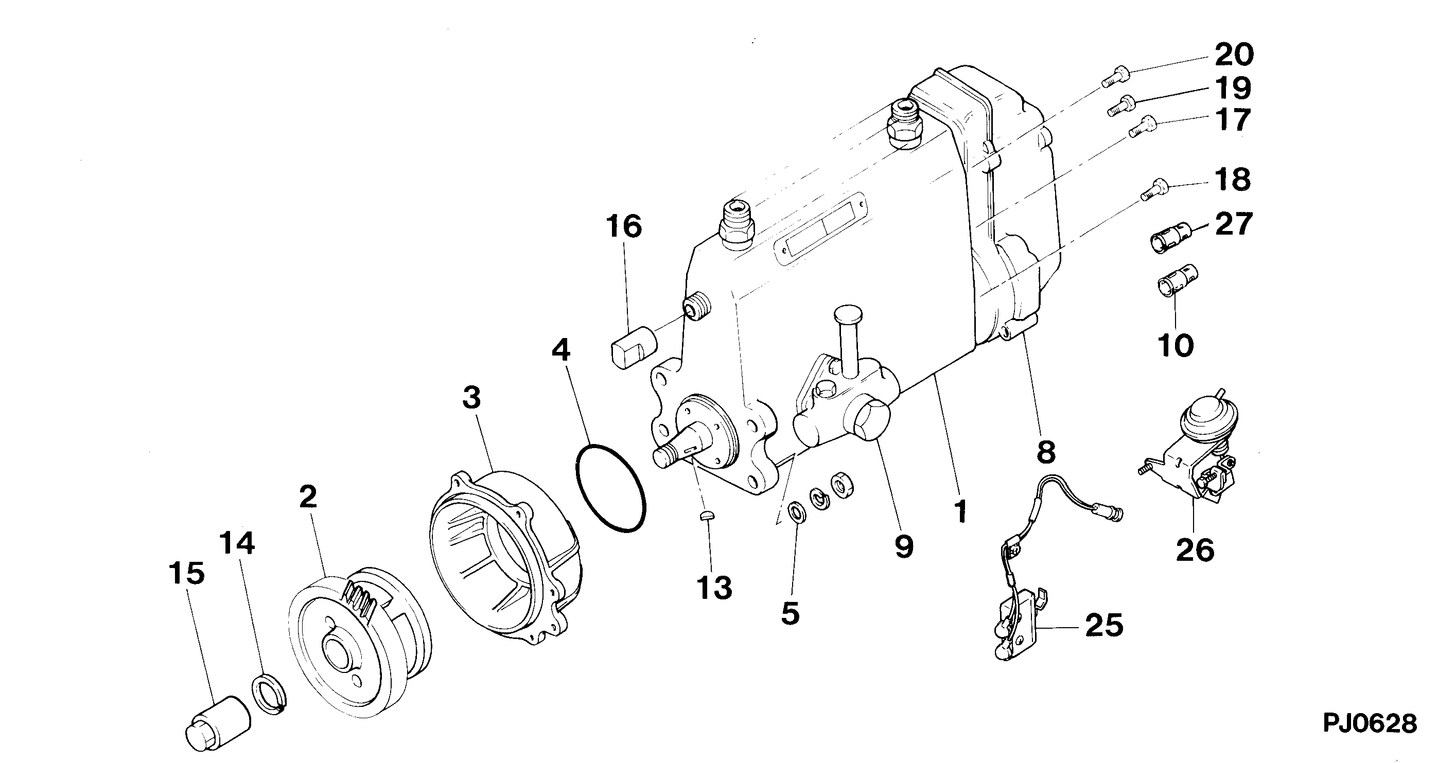
Components :
Scheme #.#:
№
Qty
Part num
Name
Remarks
Manufacture num
000
[01]
09300-01944
PUMP ASSY, INJECTI
A4,R801
9309-
ME016269
MITSUBISHI
Include in ##:
09300-01944
as PUMP ASSY, INJECTI
Cross reference number
Part num
Firm num
Firm
Name
09300-01944
ME016269
PUMP ASSY, INJECTI
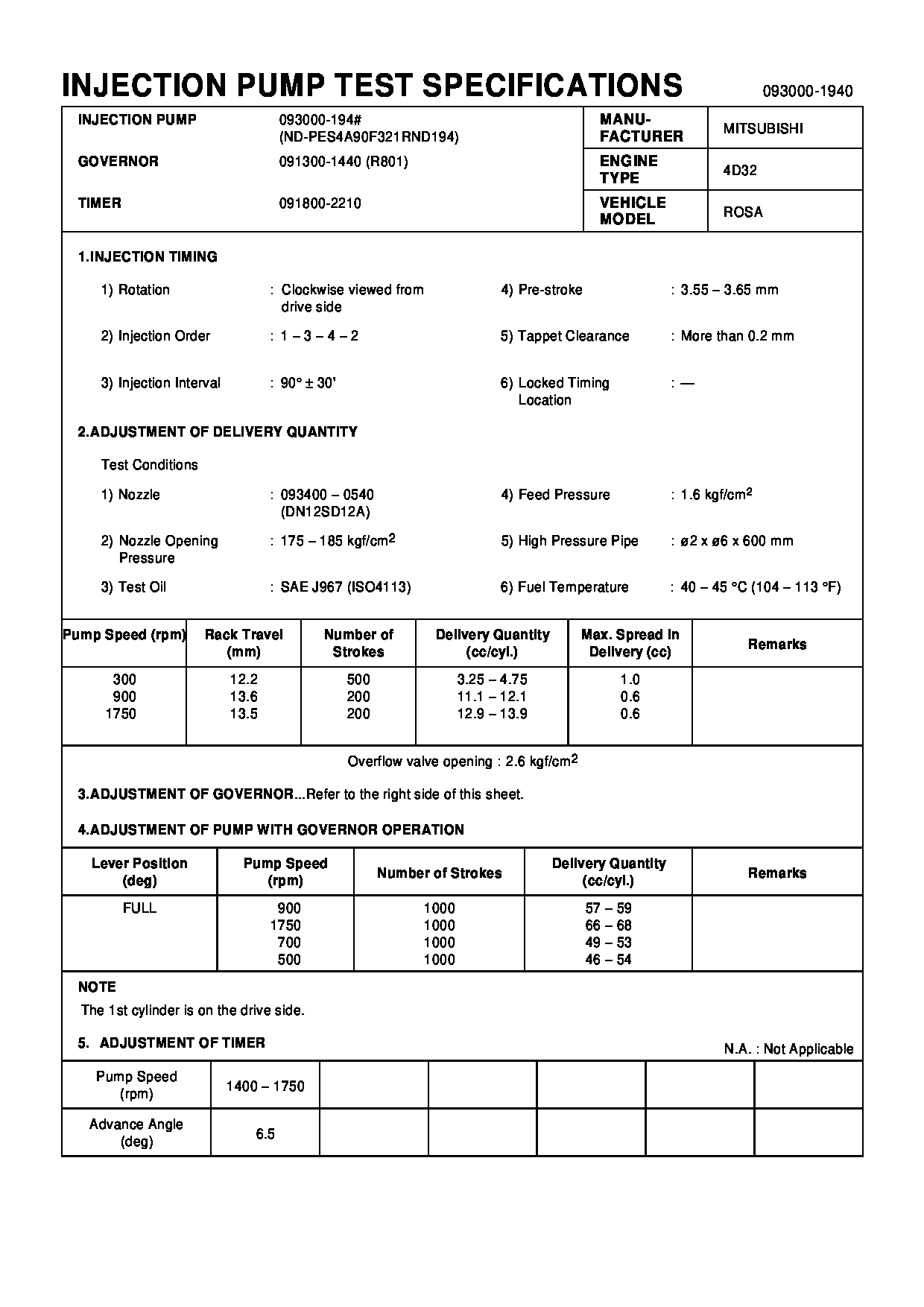
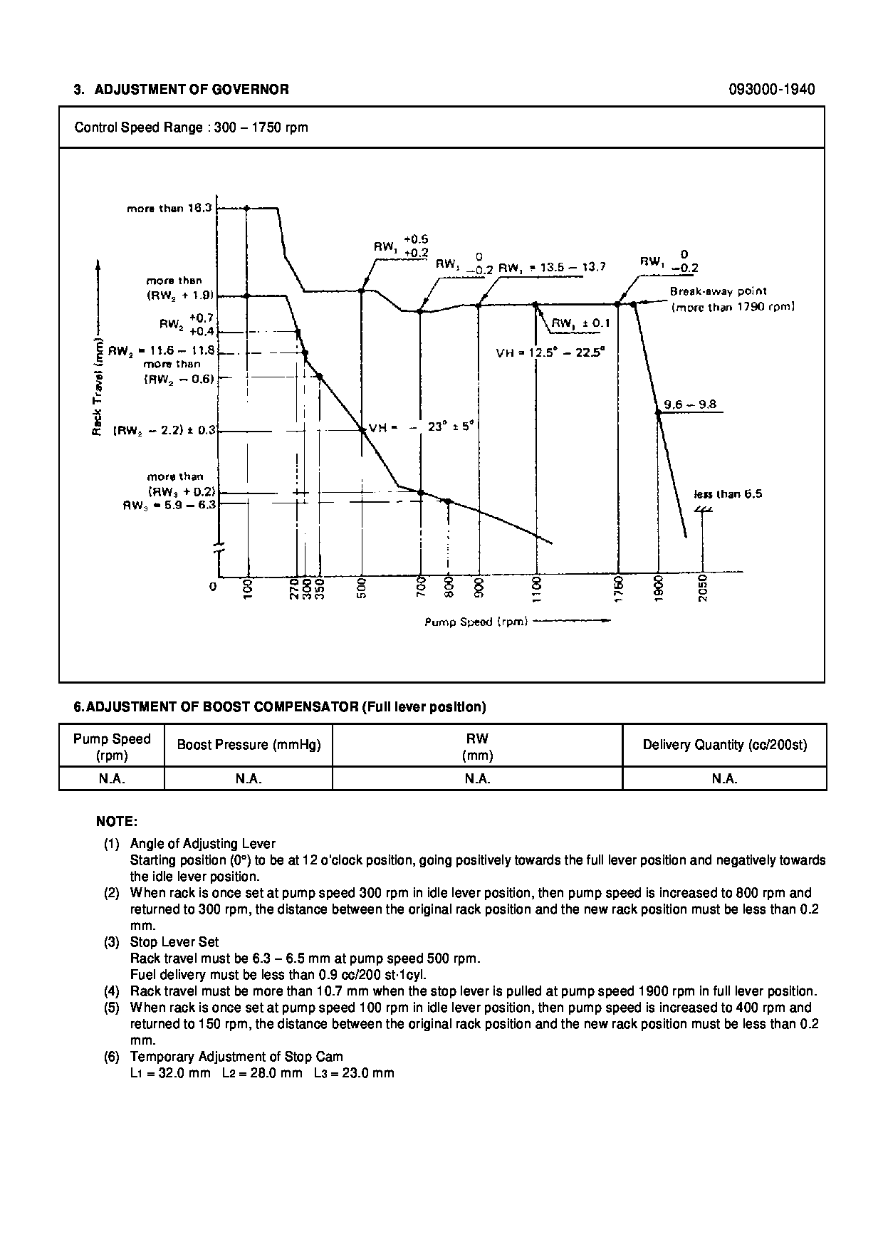
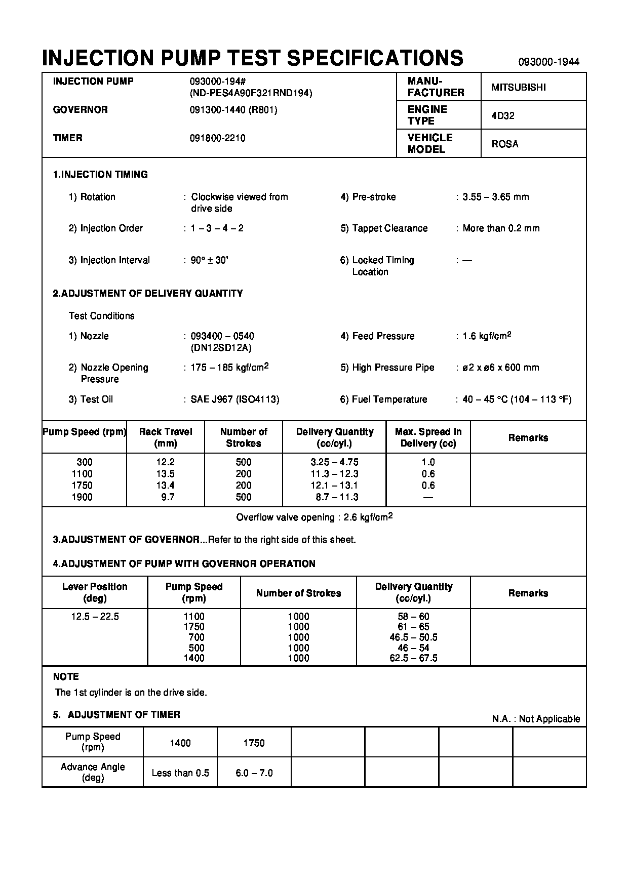
Test Calibration Data:
0930001940
ME016269
0930001944
Information:
Illustration 1 g00564355
7W-2743 Electronic Speed Switch (ESS)
(1) Push button for Overspeed Verification
(2) Reset button
(3) Overspeed indicator lamp
(4) Seal screw plug for adjusting the engine overspeed
(5) Seal screw plug for adjusting the crank terminate speed
(6) Seal screw plug for adjusting the oil step pressure speed setting The procedure for the magnetic pickup test will determine if the operation of the magnetic pickup is correct.
Connect a 6V-7070 Digital Multimeter to the "COM" terminal and the "SIG" terminal. The terminals are (ESS-3)and (ESS-4) of the ESS. Set the meter voltage scale to a scale that is greater than 1.5 VAC. Start the engine. Run the engine at low idle or 600 rpm. Choose the one that is larger. If the voltage that is measured is 1.5 VAC or more, the operation of the magnetic pickup is correct. If the voltage is less than 1.5 VAC, go to Step 2.
Stop the engine. Disconnect the wiring for the magnetic pickup at the plug-in connector. Connect the voltmeter to the connector terminals of the magnetic pickup. Start the engine. Run the engine at low idle or 600 rpm. Choose the one that is larger. If the voltage that is measured is 1.5 VAC or more, repair the wiring that is between the magnetic pickup and the ESS. If the voltage is less than 1.5 VAC, go to Step 3.
Illustration 2 g00564913
Magnetic pickup
(1) Clearance
(2) Magnetic pickup
(3) Wires to the connector
(4) Locknut
(5) Flywheel housing
(6) Ring gear
Loosen locknut (4) and turn magnetic pickup (2) in the counterclockwise direction in order to remove magnetic pickup (2) from flywheel housing (5). Turn the flywheel until a gear tooth of ring gear (6) is directly in the center of the threaded hole for magnetic pickup (2). Install magnetic pickup (2) in flywheel housing (5).
Turn magnetic pickup (2) in the clockwise direction until the end of magnetic pickup (2) slightly touches the gear tooth. Turn the magnetic pickup for one-half turn in the counterclockwise direction in order to set correct clearance (1). Tighten locknut (4) to a torque of 45 7 N m (33 5 lb ft). Note: Do not allow the magnetic pickup to turn while the locknut is tightened.
Repeat Step 2. If the voltage is still less than 1.5 VAC, replace the magnetic pickup.