Rating:
Information pump assy, injecti Denso
Product
Fuel Injection Pump
Vehicle engine
TRUCK 4D31A
Engine
4D31A
Serial start-end
8601--8607
Info
Injector Nozzle
093500-2390
Injector nozzle:
0935002390
KIT List:
Part name
Kit1
Kit2
Components :
Scheme #.#:
№
Qty
Part num
Name
Remarks
Manufacture num
Cross reference number
Part num
Firm num
Firm
Name
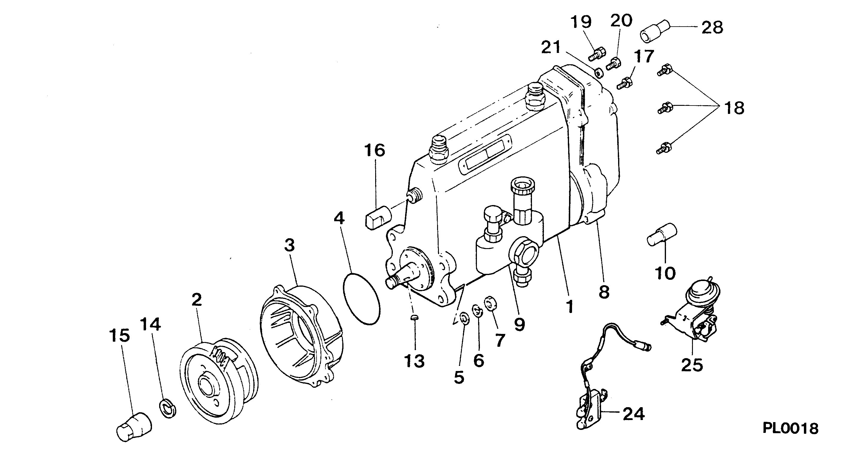
09300-01930
PUMP ASSY, INJECTI
Information:
Normal Mode
The electronic governor/control (ECM) system provides complete engine speed governing and controls cold start mode strategies, torque shaping, smoke limiting, system diagnostics and communication data links to monitor performance and diagnostic information. Warning outputs are provided for low oil pressure, low boost pressure, high coolant temperature and low coolant level with a diagnostic lamp.The purpose of normal mode is to monitor and control the genset. The GSC controls the engine according to the information received from the operator (panel switches, controls) and from the engine sensors. Some of the functions performed by the GSC while in normal mode are: engine starting, monitoring of important genset conditions, showing the operator the important genset conditions, fault detection, and engine stopping.The operator can identify normal mode by observing the display area. When in normal mode: all shutdown indicators are OFF, the fault alarm indicator is OFF and SERV is NOT displayed on the upper window. When the GSC is in normal mode, the engine is able to start or run. Refer to Engine Control, Monitoring and Protection topic for information regarding GSC control panel. In the AUTOmatic position (3 o'clock), the engine will start automatically whenever a remote initiating contact is closed. The engine will shutdown after the initiating contact opens and adjustable cooldown time elapsed. The cooldown time can be programmed to give a 0 to 30 minute cooldown period before the engine shuts down.In the MAN. START position (6 o'clock), the engine will start and run as long as the ECS switch remains in this position. In the COOLDOWN STOP position (9 o'clock), the fuel solenoid shuts the engine down, after a programmable cool down time period. In the OFF/RESET position (12 o'clock), the fault lights are reset and the engine shuts down immediately.1. Do not apply a load to the engine, or increase the speed until the oil pressure indicates normal. 2. Move the Manual Speed Potentiometer (MSP) to the (high idle-full load) position. 3. Apply the load to the driven equipment.4. Manually turn the MSP adjusting knob to change engine speed. To adjust or change engine speed droop setting, use the speed droop set screw. Control Panel Equipped Engines-Starting, Operating and Stopping
For all information regarding the generator control panel used for starting, operating and stopping the engine, refer to SR4 Generators and Control Panels Operation & Maintenance Manual, SEBU6721. Additional information and instructions are provided in the Service Manual for your specific control panel.Fuel Conservation Practices
Engine Efficiency
The efficiency of your engine can also impact fuel economy. Caterpillar engines are designed and manufactured using state-of-the-art technology to provide maximum fuel efficiency in all applications. To insure optimum performance for the life of your engine, follow the recommended operation and maintenance procedures described in this publication.* Avoid fuel spillage. Never overfill the fuel tank. Fuel expands as it warms and may overflow from the fuel tank. Keep all fuel line leaks repaired.* Use only recommended fuels with recommended heat values.* Do not idle unnecessarily. Unless