Rating:
Information pump assy, injecti Denso
Product
Fuel Injection Pump
Vehicle engine
INDUSTRIAL 4DR5P
Engine
4DR5P
Serial start-end
8601-
Info
Injector Nozzle
093500-3580
Injector nozzle:
0935003580
KIT List:
Part name
Kit1
Kit2
Components :
Scheme #.#:
№
Qty
Part num
Name
Remarks
Manufacture num
000
[01]
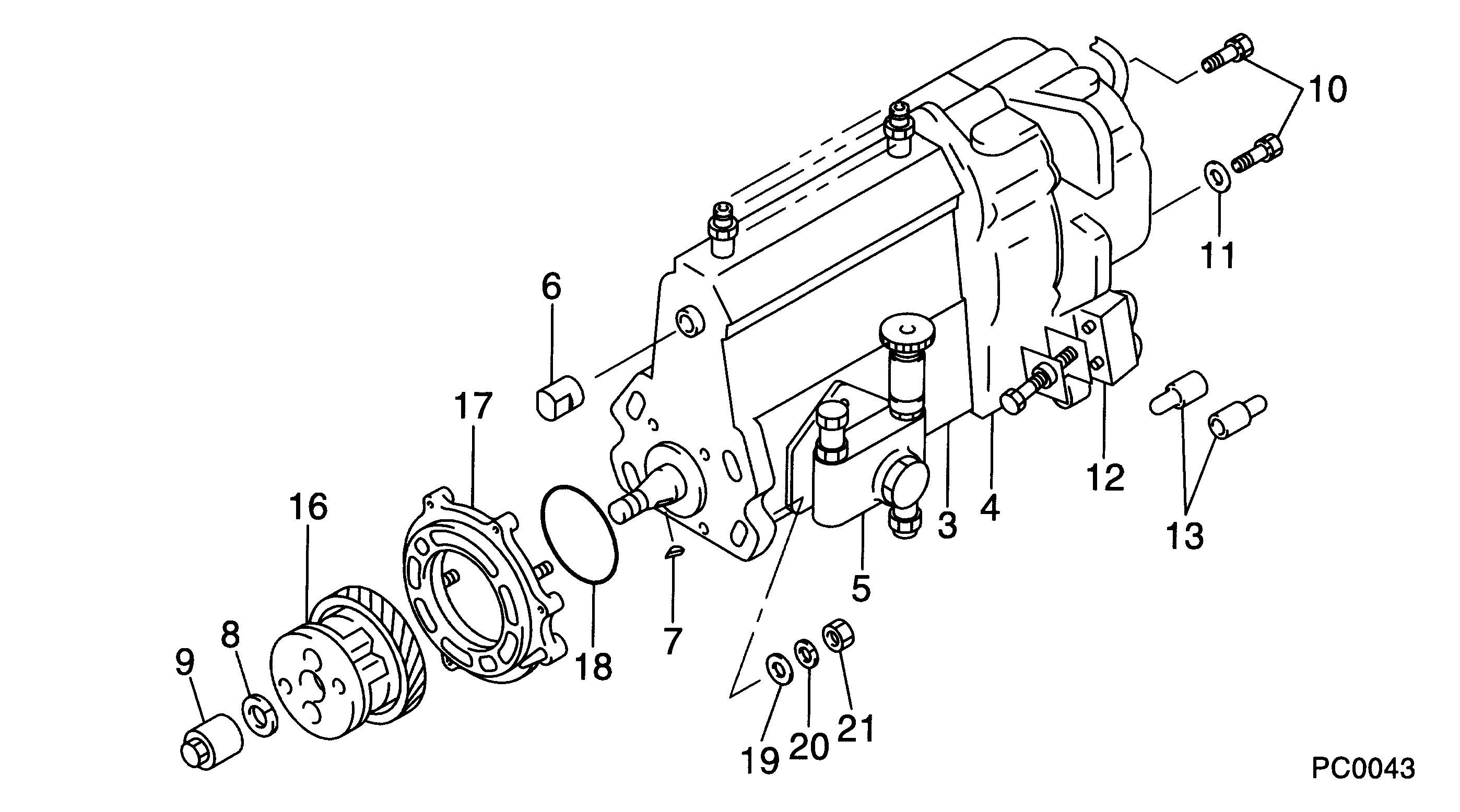
09300-01770
PUMP ASSY, INJECTI
A4,RU
Include in ##:
09300-01770
as PUMP ASSY, INJECTI
Cross reference number
Part num
Firm num
Firm
Name
09300-01770
PUMP ASSY, INJECTI
Information:
Introduction
This Special Instruction gives detailed instructions on the disassembly and assembly of the 3408E and 3412E injectors. The entire instruction should be read and understood before you begin work on the engine.Note: Contact your Caterpillar dealer to verify the current engine control software is installed for optimum injector life and engine performance.Checklist For The Proper Installation And Removal Of The Injector
All of the tools that are listed should be obtainable.
The proper sequence must be followed for the removal of the injector. This includes the use of the 131-3921 Injector Puller .
The carbon should be cleaned out of the injector sleeve. The clearance must be verified by using the 164-5924 Injector Sleeve Bore Gauge .
The proper torque procedure for the injector jumper tube and assembly must be followed.
Purge the air from the fuel lines. Check for fuel leaks and for combustion gas leakage.Failure to follow these instructions can result in failure of the tip and severe engine damage.Necessary Tools
131-3921 Injector Puller Tools For Cleaning Carbon Deposits From The Injector Sleeve Bores
4C-5027 Tap Wrench
4C-6161 Tube Brush
4C-6774 Vacuum Gun Kit
8T-7765 Surface Reconditioning Pad
1U-5512 Cut & Polish Roll
9U-6102 Reamer
9U-6862 Tapered Brush
164-5924 Injector Sleeve Bore Gauge Tools For Evacuating Fuel From The Cylinders
4C-4057 Tube
1U-5718 Vacuum Pump
1U-5814 Bottle Assembly Optional Tool
164-5927 Tube Brush Evacuating Fuel From The Fluid Manifold
Prior to removing the injector, evacuate as much fuel as possible from the manifold.
Illustration 1 g00484352
(A) Top view. (B) Front view.
Remove the fuel line (1) that is routed from the T-connector on the front of the engine to the front of the manifold.
Place the loose end of the fuel line (1) into an appropriate container in order to collect the fuel.
Use an air gun with a rubber tip in order to evacuate the fuel with pressurized air.
Place the rubber tip of the air gun in the fuel line opening of the manifold.
Approximately 138 to 207 kPa (20 to 30 psi) of pressurized air should be enough to evacuate the fuel from both manifolds without damaging the injectors.
When the fuel in the system has been evacuated, reconnect the fuel line to the manifold.
Fuel and oil will still need to be removed from the cylinder after the injectors are removed.Removal Of The Injector
The injector tip was made very hard to provide a long life. This hardness also makes the tip brittle. Side loading during the installation or striking the tip against a hard object or dropping the injector can cause the tip to break or crack. Installing an injector with a cracked tip may result in major engine damage.
After removing the injector, a certain amount of fuel and oil runs down the cylinder. Most of the fuel must be removed before the injector is reinstalled in order to avoid the possibility of hydraulic lock and severe engine damage when the engine is next cranked. In order to minimize the amount of fuel running into the cylinder, the fuel supply shutoff valve should be closed before injector removal.
Illustration 2 g00336078
This is a typical example of a 3408E Injector and a 3412E