Rating:
Information pump assy, injecti Denso
Product
Fuel Injection Pump
Vehicle engine
ROSA 4D30A
Engine
4D30A
Serial start-end
8401--8605
Info
Injector Nozzle
093500-2470
Injector nozzle:
0935002470
KIT List:
Part name
Kit1
Kit2
Components :
Scheme #.#:
№
Qty
Part num
Name
Remarks
Manufacture num
000
[01]
09300-00650
PUMP ASSY, INJECTI
A4,RU
ME016183
MITSUBISHI
Include in ##:
09300-00650
as PUMP ASSY, INJECTI
Cross reference number
Part num
Firm num
Firm
Name
09300-00650
ME016183
PUMP ASSY, INJECTI
0930000650
ME016183
MITSUBISHI
PUMP ASSY, INJECTI
Information:
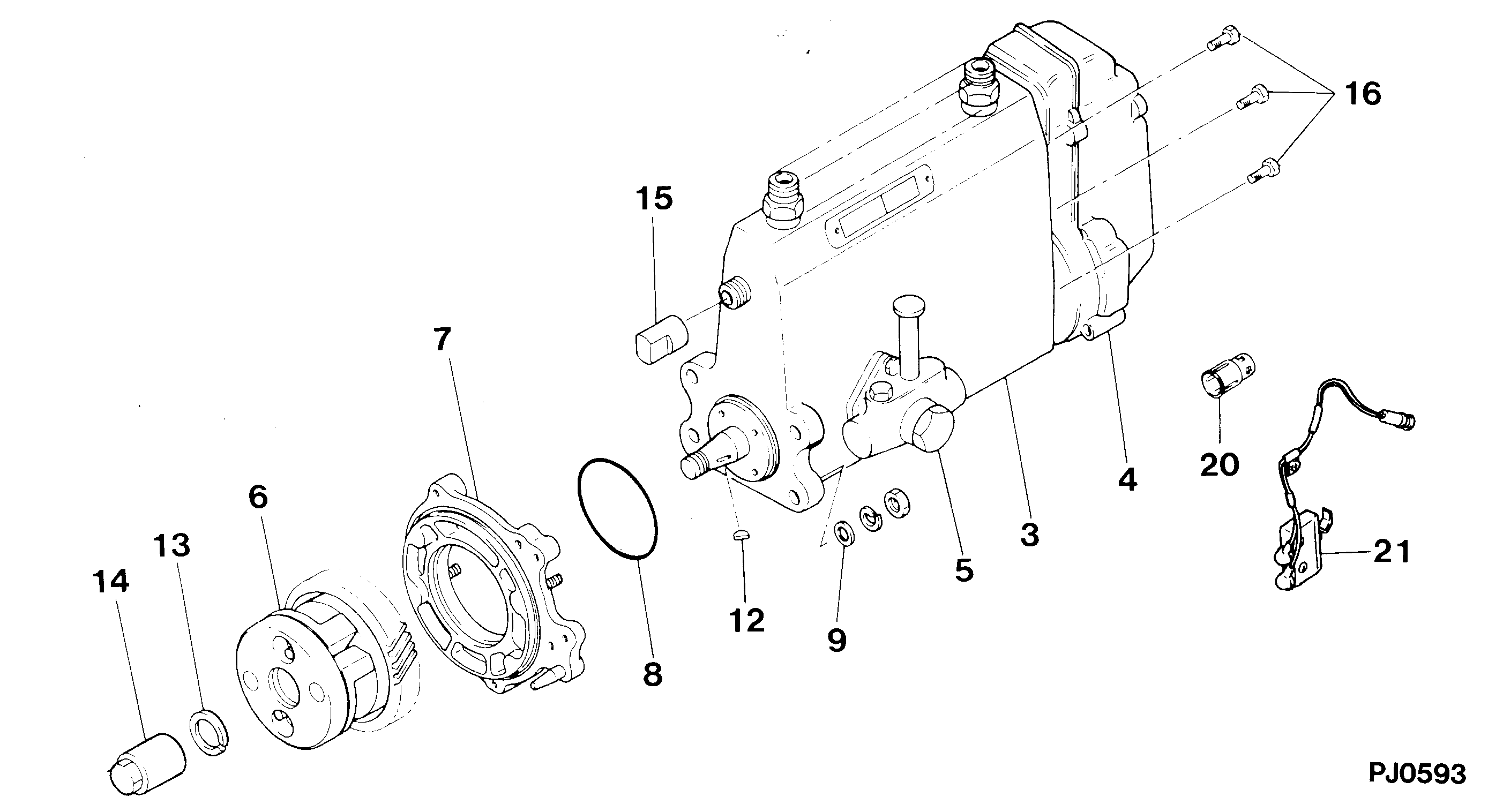
1. Disconnect fuel lines (1) from fuel transfer pump (3). Remove bolts (2). Remove fuel transfer pump (3). Remove gasket from fuel transfer pump.2. Install a new gasket on fuel transfer pump (3). Install fuel transfer pump on rear plate with the bolts (2) that hold it. Connect fuel lines (1) to the fuel transfer pump.Disassemble Fuel Transfer Pump
Start By:a. remove fuel transfer pump 1. Remove tachometer drive (3) from transfer pump cover (4).2. Remove bolts (1). Make a separation between cover (4) and pump body (2). 3. Remove lip-type seal (6) from the cover. Remove plug (5), seal, spring and plunger (bypass valve) from the cover. 4. Remove nut (10) from shaft (7). Remove gear (9) and key (11).5. Remove shaft (7) and gear (8) as a unit. Remove gear (8) from drive shaft (7) with a press.6. Remove idler gear (12). 7. Remove bushing (14), two lip-type seals and the bottom bearing from pump body (1).8. Remove check valve (13). Assemble Fuel Transfer Pump
1. Install bushing (4) in body (3) with Tooling (B). The bushing must not be extended above the (gear) surface of the body.2. Install the check valve in the body with Tooling (A).3. Install lip-type seal (5) with Tooling (C). Install the seal until it is 24.6 0.5 mm (97 .02) from the bottom surface of body (3) and with the lip toward bushing (4) as shown.4. Install lip-type seal (6) with Tooling (D). Install the seal until it is 14.2 0.5 mm (.56 .02 in) from the bottom surface of body (3) and with the lip away from seal (5) as shown.5. Install bearing (7) in body (3) with Tooling (E). The bearing must be even with the surface of the pump body. 6. Heat gear (8) to a maximum temperature of 316°C (600°F). Install gear (8) on shaft (11) until dimension (X) is 49.71 0.25 mm (1.957 0.10 in).7. Install the drive shaft and gear in body (3). Install key, gear (10) and nut (9). Tighten the nut to a torque of 28 7 N m (22 5 lb ft).8. Install idler gear (12) in body (3).9. Install lip-type seal (2) with Tooling (C). Install the seal until it is 3.8 0.5 mm (.15 .02 in) from the top surface of cover (1) with the lip toward the inside as shown. 10. Install plunger (14) (bypass valve), spring (15), seal plug (13) in pump cover (1). Tighten plug (13) to a torque of 28 4 N m (27 3 lb ft).11. Put 7M-7260 Liquid Gasket Material on the surface of cover (1). Install cover (1) on pump body.
Do not let the liquid gasket enter the pump.
The drive shaft must turn freely after the bolts that hold the transfer pump together are tightened.12. Install tachometer drive on transfer pump cover (1).End By:a. install fuel transfer pump