Rating:
Information pump assy, injecti Denso
Product
Fuel Injection Pump
Vehicle engine
LAND CRUISER 2H
Engine
2H
Serial start-end
8201--8410
Info
Injector Nozzle
093500-2370
Injector nozzle:
0935002370
KIT List:
Components :
Scheme #.#:
№
Qty
Part num
Name
Remarks
Manufacture num
000
[01]
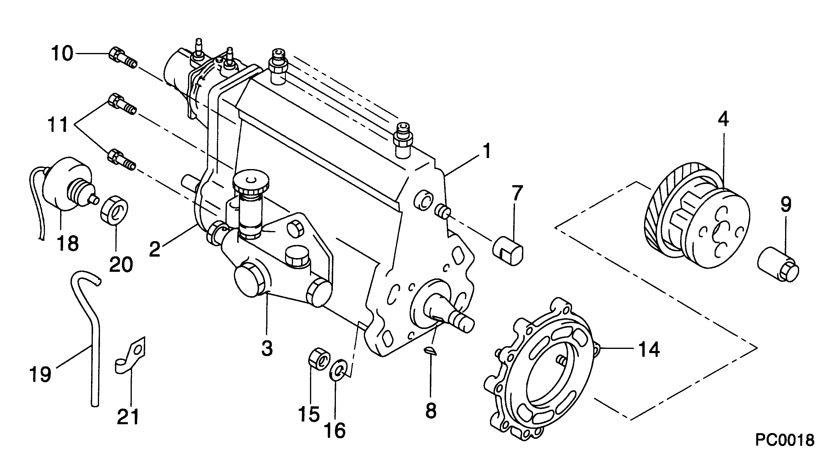
09300-00330
PUMP ASSY, INJECTI
A6,COMB
22010-68031
TOYOTA
Include in ##:
09300-00330
as PUMP ASSY, INJECTI
Cross reference number
Part num
Firm num
Firm
Name
09300-00330
22010-6803
PUMP ASSY, INJECTI
0930000330
22010-68031
TOYOTA
PUMP ASSY, INJECTI
Information:
Start By:a. remove valve cover 1. Remove the cover from the flywheel housing and install Tool (A). Turn the crankshaft with Tool (A) until there is no pressure on rocker arm (2).2. Use Tool (B) as shown to move the rocker arm away from push rod (1). Remove push rod (1). 3. Install Tool (C) on the valve lifter. Remove valve lifter (3) from the block. 4. Remove spring guide (4) from the valve lifter.5. Do Steps 1 through 4 again for the other valve lifters and push rods if necessary.Install Valve Lifters & Push Rods
Any time the valve lifter is removed from the machine, a new spring guide must be installed on the valve lifter.1. Install spring guide (1) on valve lifter (2). 2. Put the valve lifter in position on Tool (A) as shown. Make sure spring guide (1) is in position in the groove (slot) in the valve lifter as shown. 3. Use a soft hammer to install Tool (B) over spring guide (1). Make sure the groove in Tool (B) is in alignment with spring guide (1). 4. Put clean engine oil on valve lifter (2). Use Tool (B) to install the valve lifter in the engine block. Make sure the end of the spring guide is in alignment with the small hole in the block.5. When the valve lifter is in position in the block, use Tool (C) to push the valve lifter off of Tool (C). 6. Use Tool (E) to turn the crankshaft to make sure there is not pressure on the push rods and rocker arms.7. Put push rod (3) in position in the block. Use Tool (D) to move rocker arm (4) away from the push rod far enough to put push rod (3) in position under the rocker arm.End By:a. install valve cover
Any time the valve lifter is removed from the machine, a new spring guide must be installed on the valve lifter.1. Install spring guide (1) on valve lifter (2). 2. Put the valve lifter in position on Tool (A) as shown. Make sure spring guide (1) is in position in the groove (slot) in the valve lifter as shown. 3. Use a soft hammer to install Tool (B) over spring guide (1). Make sure the groove in Tool (B) is in alignment with spring guide (1). 4. Put clean engine oil on valve lifter (2). Use Tool (B) to install the valve lifter in the engine block. Make sure the end of the spring guide is in alignment with the small hole in the block.5. When the valve lifter is in position in the block, use Tool (C) to push the valve lifter off of Tool (C). 6. Use Tool (E) to turn the crankshaft to make sure there is not pressure on the push rods and rocker arms.7. Put push rod (3) in position in the block. Use Tool (D) to move rocker arm (4) away from the push rod far enough to put push rod (3) in position under the rocker arm.End By:a. install valve cover