Rating:
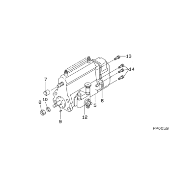
Information pump assy, injecti Denso
Product
Fuel Injection Pump
Vehicle engine
INDUSTRIAL S4S-DT
Engine
S4S-DT
Serial start-end
0611-
Info
Injector Nozzle
093500-7600
Injector nozzle:
0935007600
KIT List:
Part name
Kit1
Kit2
Components :
Scheme #.#:
№
Qty
Part num
Name
Remarks
Manufacture num
000
[01]
09200-05630
PUMP ASSY, INJECTI
A4,RSV
Include in ##:
09200-05630
as PUMP ASSY, INJECTI
Cross reference number
Part num
Firm num
Firm
Name
09200-05630
PUMP ASSY, INJECTI
Information:
1. Remove tube and elbow (1).2. Remove tube and oil sump (2). 3. Turn the crankshaft until two of the pistons are at top center and two are at bottom center.
Put identification marks on the connecting rod caps as to their location in the engine. Keep the caps with their respective piston.
4. Remove nuts (3), and remove connecting rod bearing cap (4).5. Remove the lower bearing half from the connecting rod cap. Push the connecting rod away from the crankshaft, and remove the upper bearing half.
Use tape to hold the bearing halves together and to identify the number of the cylinder.
6. Install the upper bearings in the connecting rods. Be sure the tab on the back of the bearing fits in the groove of the connecting rod. Install the connecting rod bearings dry when the clearance checks are made. Put clean engine oil on the connecting rod bearings for final assembly.7. Carefully pull the connecting rods onto the crankshaft.8. Install the lower bearings in the connecting rod caps. Be sure the tab on the back of the bearing fits the groove of the cap.9. Check the bearing clearance with Plastigage as follows:a. Put clean oil on the connecting rod bolt threads.b. Align the number on bearing cap (4) with the number on the connecting rod, and install bearing cap (4) with a line of Plastigage across the bearing.c. Install the nuts finger tight; then tighten them to a torque of 100 N m (75 lb.ft.).d. Remove the connecting rod cap, and measure the thickness of the Plastigage to the bearing clearances. See Engine Specifications for correct bearing clearances.e. Carefully move the connecting rod up enough to permit clean engine oil to be put on the upper bearing and crankshaft journal.f. Carefully pull the connecting rod onto the crankshaft.g. Install connecting rod cap (4), and tighten the nuts to the proper torque. The Cadmium plated nuts (silver color) are to be tightened to a torque of 100 N m (75 lb.ft.). The Phosphated nuts (dull black color) are to be tightened to a torque of 130 N m (95 lb.ft.).h. Repeat the procedure for the remainder of the connecting rods.10. Install tube and elbow (1) and tube and oil sump (2).End By:a. install oil pan


