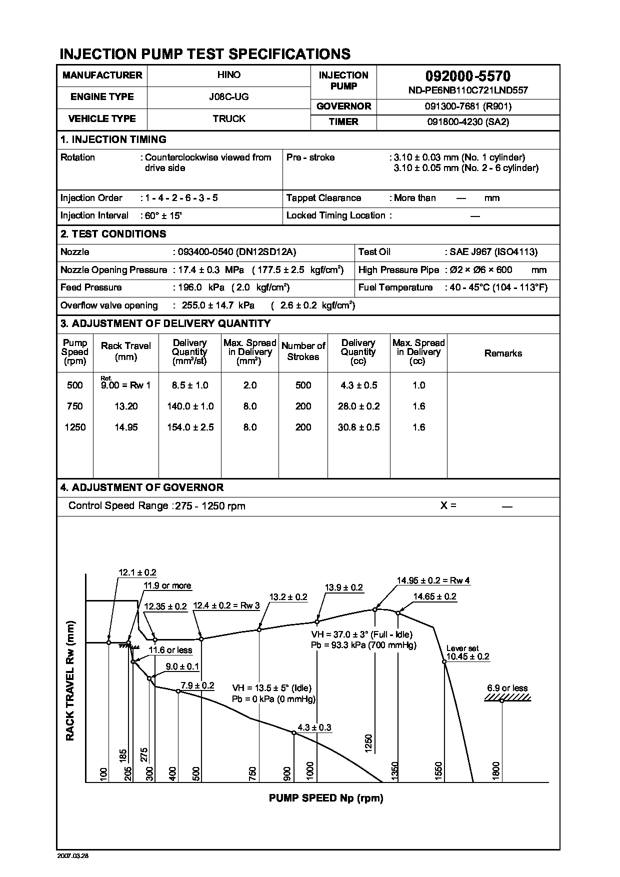
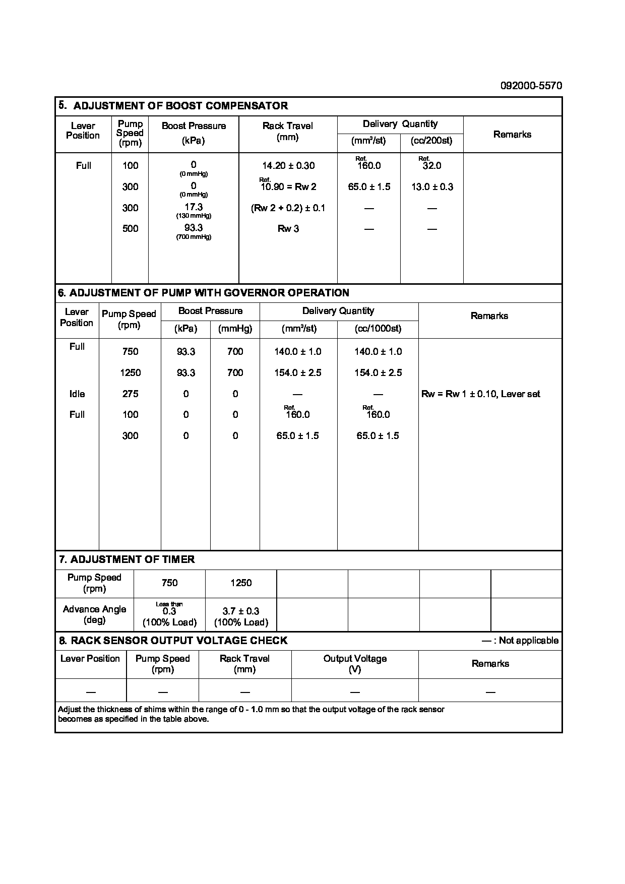
Rating:
Information pump assy, injecti Denso
Product
Fuel Injection Pump
Vehicle engine
TRUCK J08EUG
Engine
J08EUG
Serial start-end
0609-
Info
Injector Nozzle
093500-8100
Injector nozzle:
0935008100
KIT List:
Part name
Kit1
Kit2
Components :
Scheme #.#:
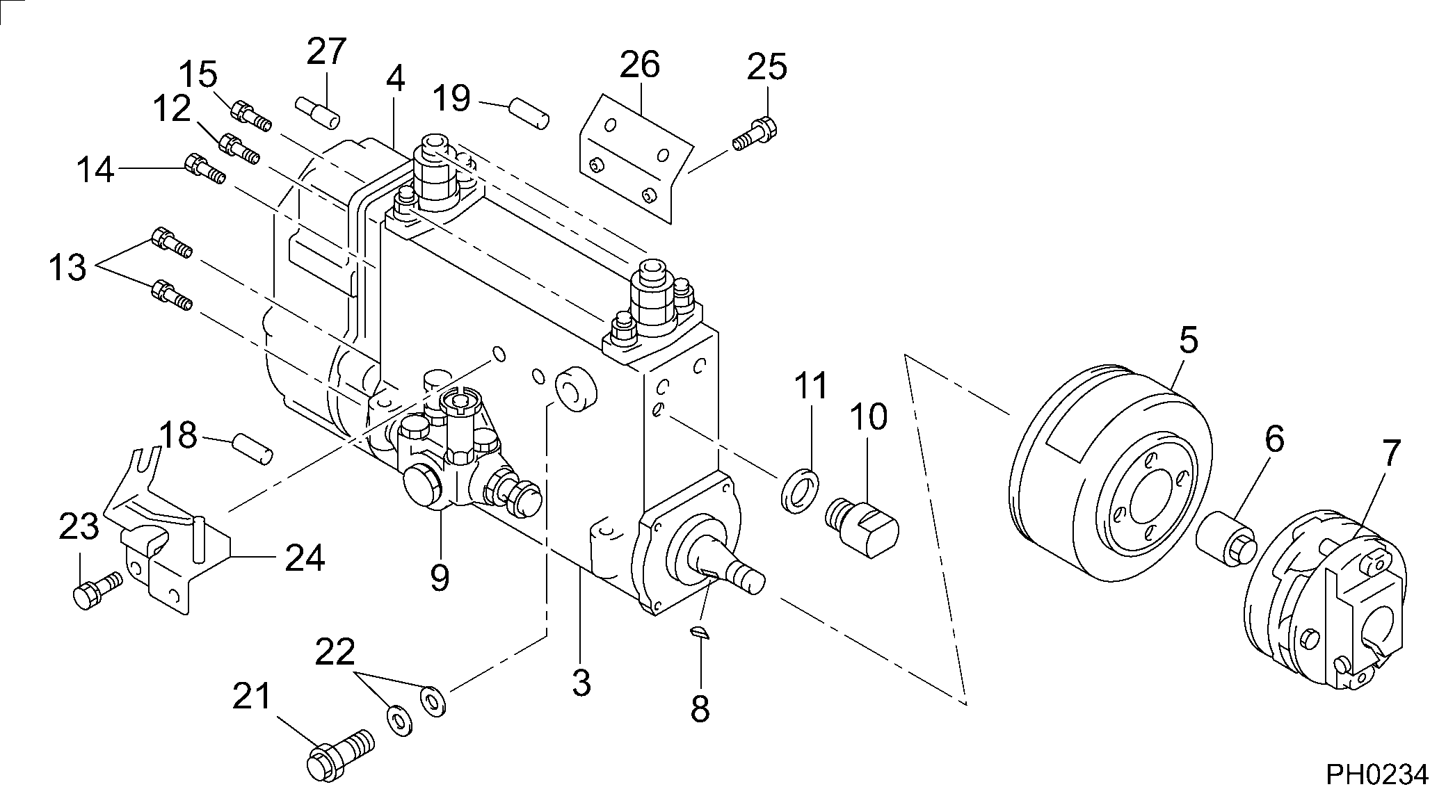
№
Qty
Part num
Name
Remarks
Manufacture num
000
[01]
09200-05570
PUMP ASSY, INJECTI
NB6,R901
22010-E0130
HINO
Include in ##:
09200-05570
as PUMP ASSY, INJECTI
Cross reference number
Part num
Firm num
Firm
Name
09200-05570
22010-E013
PUMP ASSY, INJECTI
0920005570
22010-E0130
HINO
PUMP ASSY, INJECTI
Information:
2. Remove plate (2) that holds idler gear (1). 3. Remove idler gear (1). 4. Inspect two bushings (3) in idler gear (1). See Engine Specifications for bushing diameter. Remove two bushings (3) if replacement is necessary. 5. Remove fuel injection pump drive gear (4). 6. Bend lock (5) away from the bolt. Remove the bolt and remove washer (6). 7. Remove camshaft drive gear (7) with tool (A).Install Timing Gears
1. Align the slot in gear (1) with the key in the camshaft. Put the camshaft gear in position on the camshaft. 2. Install washer (2), lock (3) and the bolt. Tighten the bolt to a torque of 60-70 N m (45-52 lb ft). Bend the tab of the lock against the bolt head. 3. Align the roll pin in fuel injection pump drive gear (4) with the hole in fuel injection pump drive shaft (5). Install fuel injection pump drive gear (4) on to fuel injection pump drive shaft (5). 4. Install three bolts (6) to hold drive gear (4) to the fuel injection pump drive shaft. 5. Use tool (A) to install two bushings (7) into idler gear (8). Install the bushings even with the outside of idler gear (8). 6. Align the timing marks on idler gear (8) with the crankshaft gear, camshaft drive gear and the fuel injection pump drive gear. 7. Install plate (9) and the bolts to hold idler gear (8) on the idler gear shaft. Tighten the three bolts to a torque of 40 N m (30 lb ft). 8. Check the idler gear end clearance. The clearance must be at least 0.25 mm (.010 in). 9. Fasten a steel plate to the timing gear case. Fasten tooling (A) to the plate as shown. Check the timing gear backlash. The backlash must be 0.08 - 0.15 mm (.003 - .006 in).
1. Align the slot in gear (1) with the key in the camshaft. Put the camshaft gear in position on the camshaft. 2. Install washer (2), lock (3) and the bolt. Tighten the bolt to a torque of 60-70 N m (45-52 lb ft). Bend the tab of the lock against the bolt head. 3. Align the roll pin in fuel injection pump drive gear (4) with the hole in fuel injection pump drive shaft (5). Install fuel injection pump drive gear (4) on to fuel injection pump drive shaft (5). 4. Install three bolts (6) to hold drive gear (4) to the fuel injection pump drive shaft. 5. Use tool (A) to install two bushings (7) into idler gear (8). Install the bushings even with the outside of idler gear (8). 6. Align the timing marks on idler gear (8) with the crankshaft gear, camshaft drive gear and the fuel injection pump drive gear. 7. Install plate (9) and the bolts to hold idler gear (8) on the idler gear shaft. Tighten the three bolts to a torque of 40 N m (30 lb ft). 8. Check the idler gear end clearance. The clearance must be at least 0.25 mm (.010 in). 9. Fasten a steel plate to the timing gear case. Fasten tooling (A) to the plate as shown. Check the timing gear backlash. The backlash must be 0.08 - 0.15 mm (.003 - .006 in).