Rating:
Information pump assy, injecti Denso
Product
Fuel Injection Pump
Vehicle engine
BUS J08
Engine
J08
Serial start-end
0504-
Info
FOR CHINA
Injector Nozzle
093500-7820
Injector nozzle:
0935007820
KIT List:
Part name
Kit1
Kit2
Components :
Scheme #.#:
№
Qty
Part num
Name
Remarks
Manufacture num
000
[01]
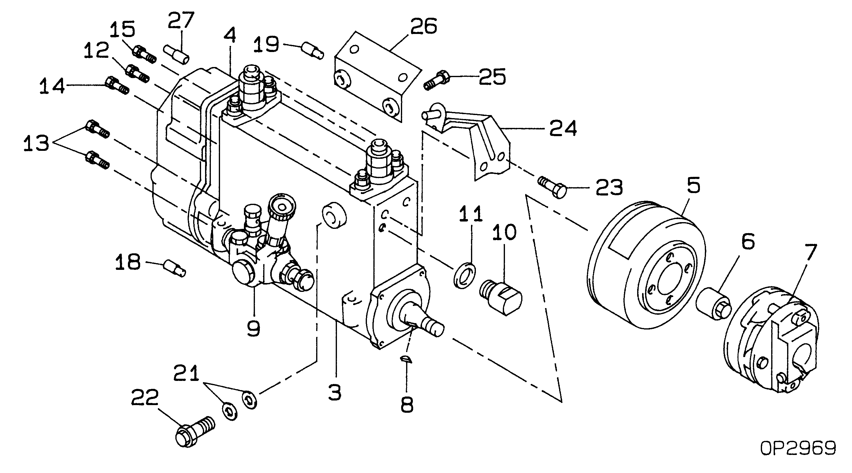
09200-05460
PUMP ASSY, INJECTI
NB6R901B
22010-9221
HINO
Include in ##:
09200-05460
as PUMP ASSY, INJECTI
Cross reference number
Part num
Firm num
Firm
Name
09200-05460
22010-9221
PUMP ASSY, INJECTI
0920005460
22010-9221
HINO
PUMP ASSY, INJECTI
Information:
1. Remove tube and elbow (1).2. Remove tube and oil sump (2).
Turn the crankshaft so the piston is down, and remove the ridge of carbon with emery cloth from each liner before removing the pistons. Damage can be caused to the pistons during removal by the build up of carbon if it is not removed.
3. Turn the crankshaft until the connecting rod cap to be removed is at bottom center.4. Remove connecting rod cap (3) from the connecting rod.
Put identification marks on the connecting rod caps as to their location in the engine. Keep the caps with their respective piston.
5. Push the connecting rod and piston away from the crankshaft until the piston rings are above the cylinder liner. Remove piston (4) and the connecting rod from the engine.
Use tape to hold the bearing halves together and to identify the number of the cylinder.
Install Pistons
1. Turn the crankshaft until the bearing journal for the piston to be installed is at bottom center.2. Put clean engine oil on the crankshaft journal and on the inside of the cylinder liner.3. Put clean engine oil on the piston rings and connecting rod bearings.4. Move the piston ring gaps 180° apart.5. Use tool (A), and put the piston and connecting rod in its original location in the cylinder block. Be sure the numbered side of the connecting rod is toward the right side of the engine. This is when viewed from the front of the engine.
Be sure the connecting rod bolts do not contact the crankshaft journal during installation of the piston.
6. Use a hammer handle, and lightly tap the piston into position.
When the connecting rod caps are installed, make sure the number on the side of the cap is next to the same number on the connecting rod. The numbers must be away from the camshaft.
7. Install connecting rod cap (1) and the nuts which hold it. Tighten the nuts to a torque value of: Cadmium plated nuts (silver color) - 100 N m (75 lb.ft).Phosphated nuts (dull black color) - 130 N m (95 lb.ft.).8. Follow the same procedure for installation of the remainder of the pistons. 9. Install tube and elbow (2). Install tube and oil sump (3).End By:a. install oil panb. install cylinder head assemblyDisassemble Pistons
Start By:a. remove pistons Put identification marks on all parts for correct assembly.1. Remove rings (1) from piston (2) with tool (A). 2. Remove retaining ring (3) from each side of the piston with tool (B).3. Remove pin (4) and connecting rod (5) from piston (2). 4. Remove bolts (7) from the connecting rod.5. Remove bushing (6) from connecting rod (5) with tool group (C).6. Check all of the parts of the piston and rod for damage and wear. See Specification for minimum and maximum wear dimensions.Assemble Pistons
1. Install bolts (1) in connecting rod (2).2. Install the bushing in connecting rod (2) with tool group (A) and a press. Hone the bushing to the correct size. See Specifications for the correct dimension. 3.