Rating:
Information pump assy, injecti Denso
Product
Fuel Injection Pump
Vehicle engine
INDUSTRIAL S6S-DT
Engine
S6S-DT
Serial start-end
0308-
Info
Injector Nozzle
093500-7600
Injector nozzle:
0935007600
KIT List:
Part name
Kit1
Kit2
Include in ##:
Cross reference number
Part num
Firm num
Firm
Name
09200-05360
PUMP ASSY, INJECTI
Information:
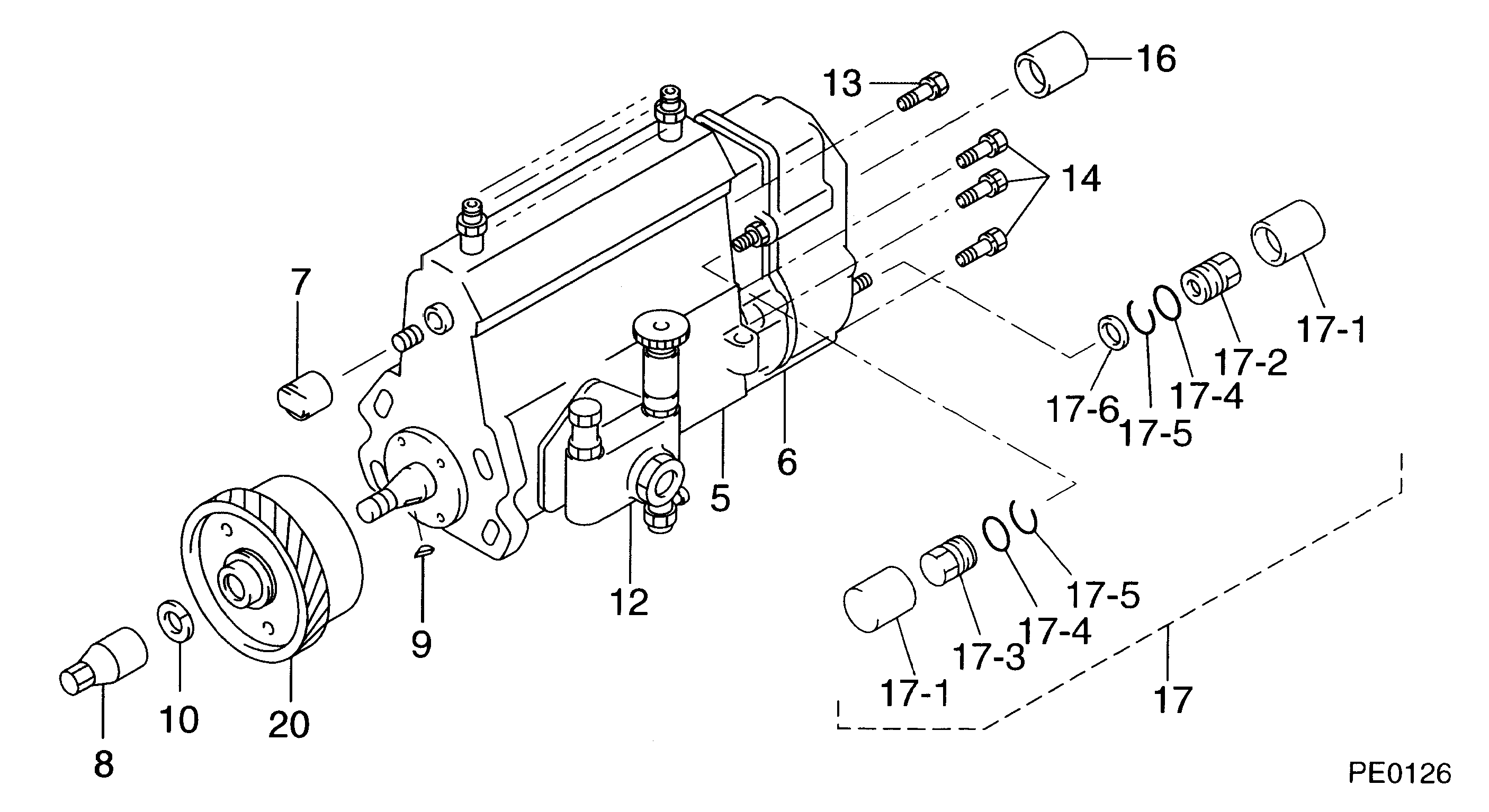
1. Disconnect two Fuel lines (1).2. Remove four bolts (2) and remove fuel transfer pump and gasket. The following steps are for the installation of the fuel transfer pump.3. Position the gasket and fuel transfer pump then install bolts (2).4. Connect fuel lines (1).5. Prime the fuel system. See the MAINTENANCE MANUAL.Disassemble Fuel Transfer Pump
Start By:a. remove fuel transfer pump 1. Remove cover (1) from the fuel transfer pump. 2. Remove strainer (2). 3. Remove valve housing (3) from body (4). 4. Use a pencil grinder to remove the staked metal that holds inlet check valve (6) and outlet check valve (5) in place. Remove check valves (5) and (6). 5. Push the center of the diaphragm down and turn it 90° to disengage the actuator rod from the actuator arm. Remove diaphragm (7). 6. Remove spring (8). 7. Remove retainer (9). 8. Remove lever (12), shaft (11) and arm (10) as an assembly. 9. If necessary, remove washers (13) from shaft (11). Remove shaft (11) and separate arm (10) from lever (12). 10. If necessary, remove primer (14) and spring.11. Thoroughly inspect all parts of the fuel transfer pump. A repair kit is available to rebuild the fuel transfer pump. The following steps are for the assembly of the fuel transfer pump. 12. Install primer (14) and the spring on to body (4). 13. Install lever (12) into arm (10) and install pin (11) through the arm and lever. Put washer (13) on each side of arm (10). 14. Put spring (15) into position on the boss in body (4). Install arm (10) and lever (12) as an assembly into body (4). Be sure spring (15) engages with the tang on lever (12). 15. Install two retainers (9) to hold shaft (11) and arm and lever assembly in body (4). 16. Install spring (8) into body (4). 17. Install diaphragm (7) into body (4). Put the flat on the actuator rod in alignment with lever (12). Push the center of the diaphragm down and turn it 90° to engage the actuator rod with the actuator arm. 18. Install a gasket and check valve (6) and gasket and check valve (5) in valve body (3). Stake valve body (3) around each check valve to hold them in position. Make the stake marks at a different location than the original stake marks. 19. Put the valve body in place on diaphragm (7) and install the screws that hold it. 20. Put strainer (2) in position on valve body (3). 21. Install a new gasket in cover (1) and Install cover (1) on body.End By:a. install fuel transfer pump
Start By:a. remove fuel transfer pump 1. Remove cover (1) from the fuel transfer pump. 2. Remove strainer (2). 3. Remove valve housing (3) from body (4). 4. Use a pencil grinder to remove the staked metal that holds inlet check valve (6) and outlet check valve (5) in place. Remove check valves (5) and (6). 5. Push the center of the diaphragm down and turn it 90° to disengage the actuator rod from the actuator arm. Remove diaphragm (7). 6. Remove spring (8). 7. Remove retainer (9). 8. Remove lever (12), shaft (11) and arm (10) as an assembly. 9. If necessary, remove washers (13) from shaft (11). Remove shaft (11) and separate arm (10) from lever (12). 10. If necessary, remove primer (14) and spring.11. Thoroughly inspect all parts of the fuel transfer pump. A repair kit is available to rebuild the fuel transfer pump. The following steps are for the assembly of the fuel transfer pump. 12. Install primer (14) and the spring on to body (4). 13. Install lever (12) into arm (10) and install pin (11) through the arm and lever. Put washer (13) on each side of arm (10). 14. Put spring (15) into position on the boss in body (4). Install arm (10) and lever (12) as an assembly into body (4). Be sure spring (15) engages with the tang on lever (12). 15. Install two retainers (9) to hold shaft (11) and arm and lever assembly in body (4). 16. Install spring (8) into body (4). 17. Install diaphragm (7) into body (4). Put the flat on the actuator rod in alignment with lever (12). Push the center of the diaphragm down and turn it 90° to engage the actuator rod with the actuator arm. 18. Install a gasket and check valve (6) and gasket and check valve (5) in valve body (3). Stake valve body (3) around each check valve to hold them in position. Make the stake marks at a different location than the original stake marks. 19. Put the valve body in place on diaphragm (7) and install the screws that hold it. 20. Put strainer (2) in position on valve body (3). 21. Install a new gasket in cover (1) and Install cover (1) on body.End By:a. install fuel transfer pump