Rating:
Information pump assy, injecti Denso
Product
Fuel Injection Pump
Vehicle engine
BUS 6D16T2
Engine
6D16T2
Serial start-end
0001-
Info
Injector Nozzle
093500-6780
Injector nozzle:
0935006780
KIT List:
Part name
Kit1
Kit2
Components :
Scheme #.#:
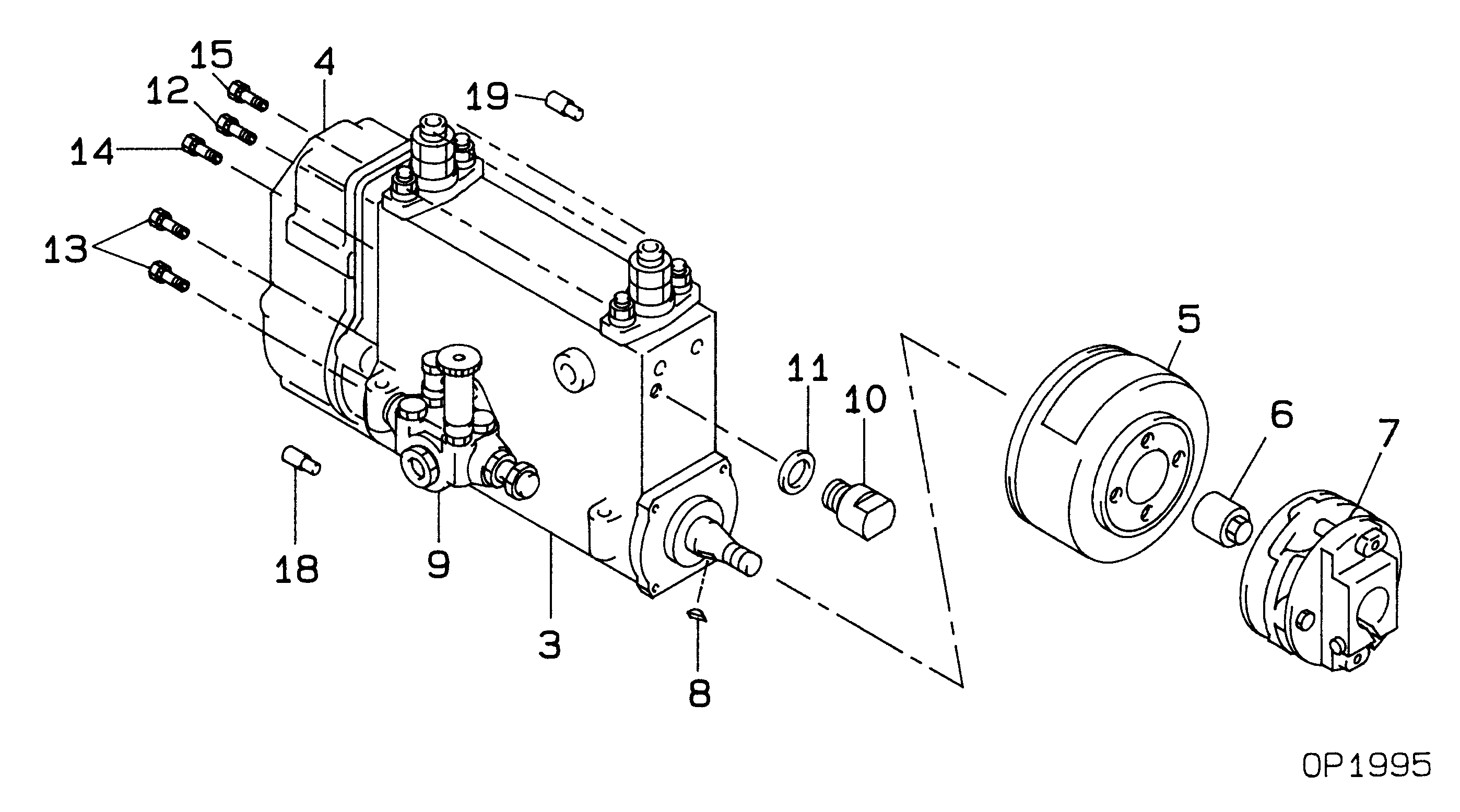
№
Qty
Part num
Name
Remarks
Manufacture num
000
[01]
09200-04410
PUMP ASSY, INJECTI
NB6,R901
ME170536
MITSUBISHI
Include in ##:
09200-04410
as PUMP ASSY, INJECTI
Cross reference number
Part num
Firm num
Firm
Name
09200-04410
ME170536
PUMP ASSY, INJECTI
0920004410
ME170536
MITSUBISHI
PUMP ASSY, INJECTI
Information:
Typical Example1. Fasten the engine on Tool (A). The weight of the engine is 1362 kg (3000 lb).2. Remove the bolts and nuts that hold air cleaner group (1), pipe assembly (3), bracket assembly (4) and lifting plate (5) as a unit to the engine. Fasten a hoist to the unit and remove it from the engine. The weight of the unit is approximately 39 kg (85 lb).3. Remove tube assembly (2) from the engine.
Typical Example4. Install the two bolts to hold the primary fuel filter bracket (6) in place while the engine is turned with Tool (A). 5. Turn the engine to the position shown with Tool (A). Remove rod bearing caps (8) from the ends of the connecting rods. Push the connecting rods away from the crankshaft.6. Remove the bolts and remove main bearing caps (7) from the crankshaft. 7. Remove thrust plates (9) from the center main bearing journal. 8. Fasten a hoist to crankshaft (10) with tooling (B). Remove crankshaft (10) from the engine block. The weight of the crankshaft is 159 kg (350 lb). 9. Use Tool (C) to remove outer gear (2) from the end of the crankshaft.10. Use a hammer and chisel to remove the spacer from the crankshaft. 11. Use Tool (D) to remove the gear alignment dowel from the crankshaft.12. Use Tool (C) to remove inner gear (11) from the end of the crankshaft. If new main bearings are not to be installed, put identification on the old main bearings as to their location in the cylinder block and to which main bearings caps they belong.13. Remove main bearings (13) from the cylinder block and the main bearing caps.Install Crankshaft
1. If the dowel was removed from the flywheel end of the crankshaft, install it in the crankshaft to a maximum dimension of 6.4 mm (.25 in).2. Heat the crankshaft gears to a maximum temperature of 205° C (400° F).3. The centerline of inner gear key must be in alignment with the centerline of the dowel hole within 0.51 mm (.020 in). Install crankshaft inner gear (14) on the crankshaft.4. Install the spacer on the crankshaft.5. Install the dowel in the crankshaft. The dowel must be extended no more than 4.1 0.5 mm (.16 .02 in) from the surface of the crankshaft. The dowel in the crankshaft must be in alignment with the notch in crankshaft gear (15).6. Make sure the "V" mark on the crankshaft gear is toward the outside, and install crankshaft gear (15). 7. Thoroughly clean the cylinder block and main bearing caps.
Make sure the upper and lower halves of the main bearings are installed so the bearing tabs fit into the notch in the cylinder block and main bearing caps.
Install the main bearings dry when the clearance checks are made. Put clean engine oil on the main bearings for final assembly.8. Install the upper half of main bearings (13) (bearings with oil holes) in the cylinder block.9. Fasten a hoist to crankshaft (10) with