Rating:
Information pump assy, injecti Denso
Product
Fuel Injection Pump
Vehicle engine
BUS J08C-TI
Engine
J08C-TI
Serial start-end
0001-
Info
Injector Nozzle
093500-6650
Injector nozzle:
0935006650
KIT List:
Part name
Kit1
Kit2
Components :
Scheme #.#:
№
Qty
Part num
Name
Remarks
Manufacture num
000
[01]
09200-04310
PUMP ASSY, INJECTI
NB6,R901
-0706
22010-8710
HINO
000
[01]
09200-04310
PUMP ASSY, INJECTI
NB6,R901
0706-
S2201-08710-D
HINO
Include in ##:
09200-04310
as PUMP ASSY, INJECTI
09200-04310 PUMP ASSY, INJECTI
Cross reference number
Part num
Firm num
Firm
Name
09200-04310
22010-8710
PUMP ASSY, INJECTI
0920004310
22010-8710
HINO
PUMP ASSY, INJECTI
0920004310
S2201-08710-D
HINO
PUMP ASSY, INJECTI
Information:
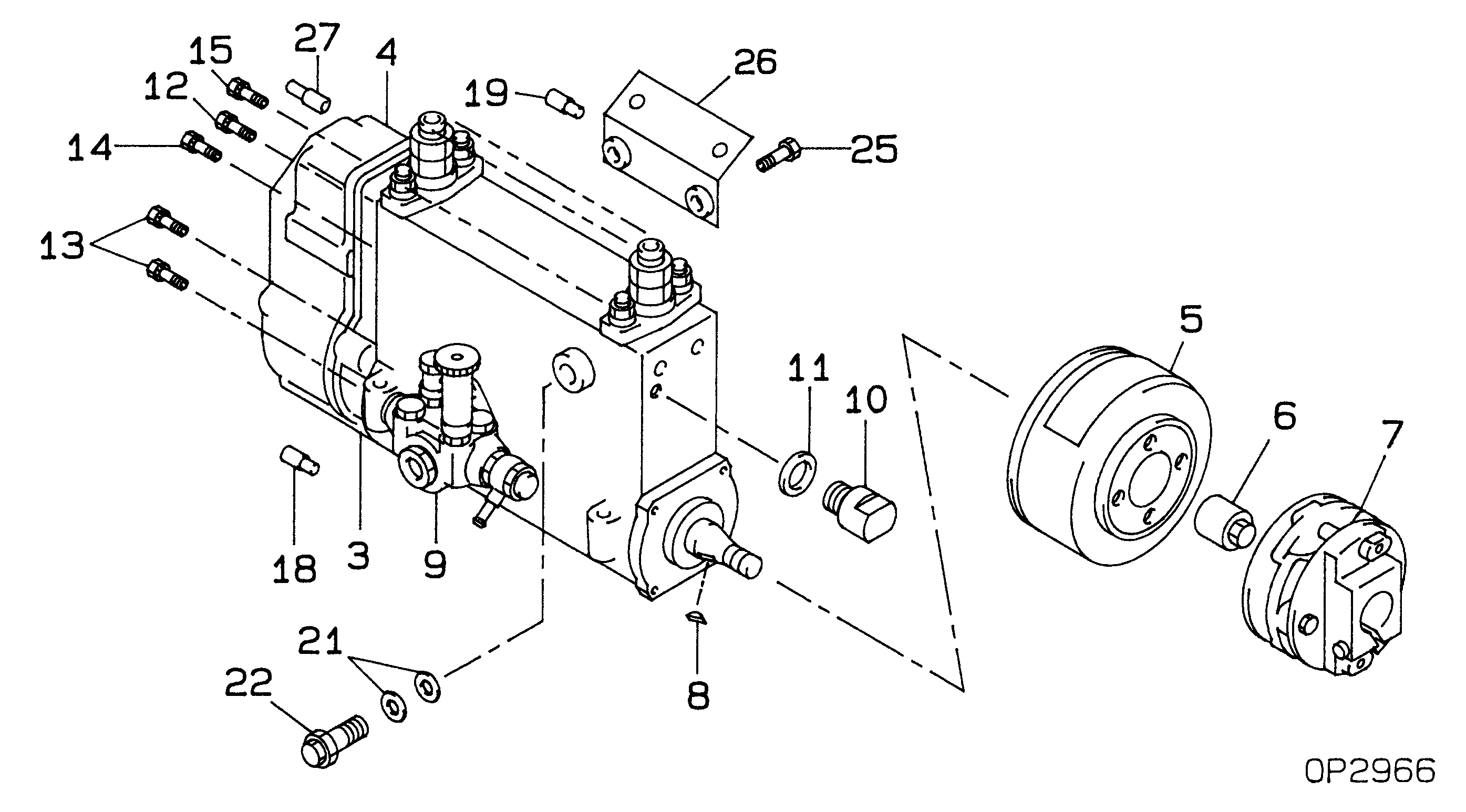
1. Install the fuel injection pump housing on tool (A). 2. Remove the bolt (1) from the cover. Turn the injection pump camshaft until the timing pin (B) can be installed in the camshaft.3. Install tool (C) in the threads of the sleeve (3). Tighten the bolt until the sleeve can be removed.4. Remove the four bolts (4) that hold the body to the housing.5. Remove the body (2) from the housing. 6. Remove the idler gear (5) from the body.7. Remove the O-ring seal (6) from the body. Remove the two lip type seals (7) from the body. 8. Remove the drive gear (9) from the shaft.9. Remove the key (8) from the shaft.Install Fuel Transfer Pump
1. Install the key (1) and the drive gear (2) on the shaft.2. Put 5S1454 Sealing Compound on the outside diameter of the seals. 3. Install the inner seal in the body with the lip of the seal toward the inside with tooling (A).4. Install the outer seal in the body with the lip of the seal toward the outside with tooling (B).5. Remove the extra sealing compound from the body and the seals after installation. 6. Install the O-ring seal (4) and the idler gear (3) in the body. 7. Install the body (5) on the housing. 8. Install the four bolts (7) that hold the body to the housing.9. Put the timing pin (D) in position to keep the camshaft from turning.10. Put the sleeve (6) on the camshaft. 11. Tighten the sleeve into position on the shaft with 4B4280 Washer of tooling (C) approximately .25 in. (6.4 mm). Tighten the sleeve the remainder of the way with the 4N3371 Washer. The 4N3371 Washer is the washer which is on the tachometer drive bolt.
Do not hit the sleeve to install. Damage to governor will result.
12. The end play of the camshaft must be .023 .018 in. (0.58 0.46 mm) after sleeve (6) is installed.end by: a) install fuel injection pump housing and governor