Rating:
Information pump assy, injecti Denso
Product
Fuel Injection Pump
Vehicle engine
TRUCK J08C
Engine
J08C
Serial start-end
9910-
Info
Injector Nozzle
093500-6640
Injector nozzle:
0935006640
KIT List:
Part name
Kit1
Kit2
Components :
Scheme #.#:
№
Qty
Part num
Name
Remarks
Manufacture num
000
[01]
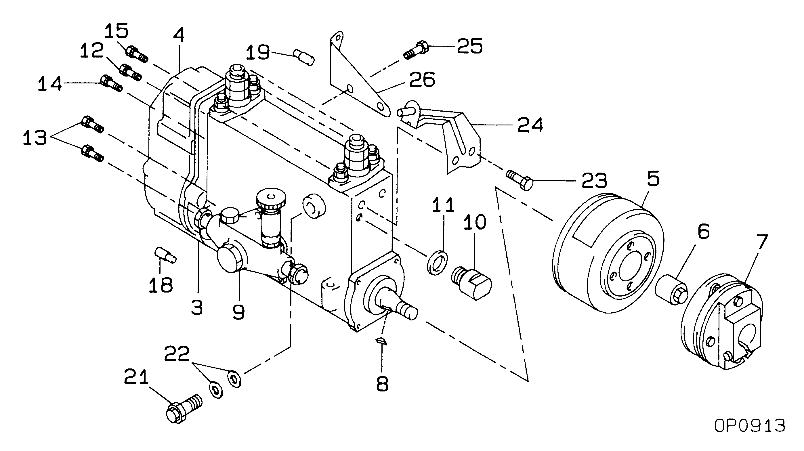
09200-04290
PUMP ASSY, INJECTI
NB6,R801
22010-8730
HINO
Include in ##:
09200-04290
as PUMP ASSY, INJECTI
Cross reference number
Part num
Firm num
Firm
Name
09200-04290
22010-8730
PUMP ASSY, INJECTI
0920004290
22010-8730
HINO
PUMP ASSY, INJECTI

Information:
Typical Example1. Remove bolts (1) and cover (2). Remove bolts (3) and cover (4).
Typical Example2. Remove bolts (5) and adapter (6). Be sure that gear stays in place. Remove bolts (7) and cover (8). Keep gear in place.
Typical Example3. Remove gears (9) and crankshaft gear (10). Remove bolts (11) and idler gear (12) with retainer. Remove bolts (13) and idler gear (14) with retainer.
Typical Example4. Secure strap and a hoist to housing (15). Remove hose assembly (16) and small bolts (17) and large bolts (18). 5. Remove bolts (19) that connect housing to oil pan (20). Remove housing from cylinder block. The weight of housing is approximately 105 kg (230 lb). 6. Check O-ring seal (21) and bearing (22) on adapter and replace if necessary. 7. Check bearing (23) and O-ring seal (24) on cover and replace if necessary. 8. Remove retainer (25) from gear (9) and check bearings (26) and replace if necessary. The following steps are for the installation of the flywheel housing.9. Thoroughly clean the contact surfaces of the cylinder block and flywheel housing. Install a new gasket between the flywheel housing and the cylinder clock.10. Secure strap and a hoist to the flywheel housing, put flywheel housing in position on the cylinder block. 11. Install the bolts that hold the flywheel housing to the cylinder block. Tighten bolts 1 thru 22 in number sequence to a torque of 40 10 N m (30 7 lb ft). Tighten bolts 1 thru 9 in number sequence again to a torque of 135 20 N m (100 15 lb ft). Tighten bolts 10 thru 22 in number sequence again to a torque of 55 10 N m (40 7 lb ft).12. Install bolts that connect housing to oil pan.13. Cut flywheel housing gasket off even with the cylinder block surface. Remove excess sealant.End By:a. install crankshaft rear seal and wear sleeveb. install starting motor