Rating:
Information pump assy, injecti Denso
Product
Fuel Injection Pump
Vehicle engine
TRUCK J05C
Engine
J05C
Serial start-end
9903-
Info
Injector Nozzle
093500-6640
Injector nozzle:
0935006640
KIT List:
Part name
Kit1
Kit2
Components :
Scheme #.#:
№
Qty
Part num
Name
Remarks
Manufacture num
000
[01]
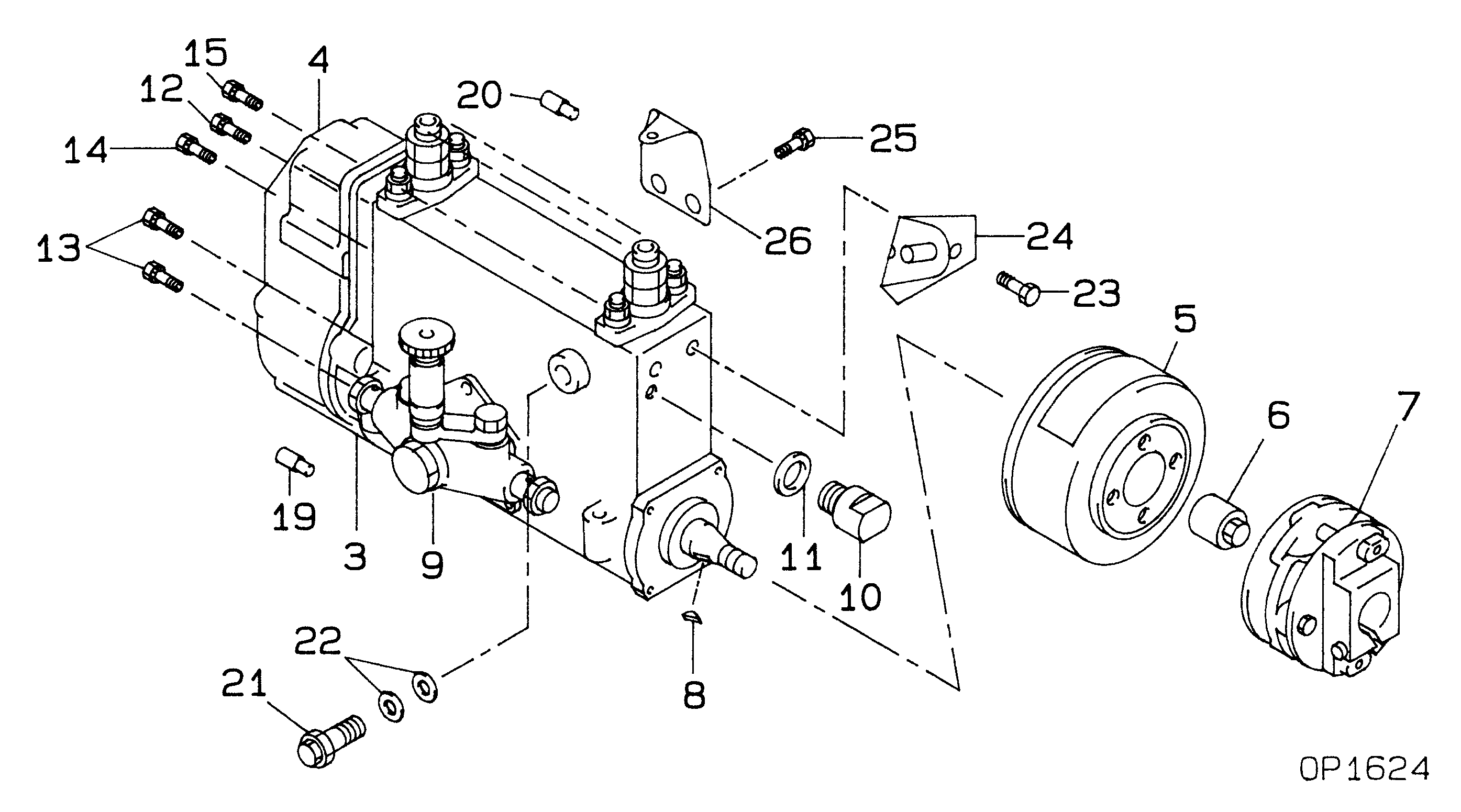
09200-04050
PUMP ASSY, INJECTI
NB4R801H
22010-8690
HINO
Include in ##:
09200-04050
as PUMP ASSY, INJECTI
Cross reference number
Part num
Firm num
Firm
Name
09200-04050
22010-8690
PUMP ASSY, INJECTI
0920004050
22010-8690
HINO
PUMP ASSY, INJECTI

Information:
2. Loosen clamp (1).3. Remove two bolts (2).4. Remove two bolts (3) and washers.5. Remove water pump (4) and the gasket. When installing replace the gasket. Make sure all gasket surfaces are clean and free of dirt. For installation of the water pump, reverse the removal steps.6. Fill the radiator with coolant to the proper level. See the Operation & Maintenance Manual.Disassemble & Assemble Water Pump
The following tools are needed for disassembly. Start By:a. remove water pump 1. Remove bolt (15) and the washer. Remove bearing (12) and gear (10) as a unit.2. Use Tool (A), (C) and a press, and remove bearing (12) from gear (10).3. Remove snap ring (8) with Tool (B).4. Remove two bolts (1), the washers, cover (14) and gasket (2) from water pump housing (18).5. Loosen bolt (13) approximately 6.4 mm (.25 in). Hit the bolt with a soft hammer to loosen impeller (16) from shaft (9).6. Remove bolt (13), washer (11), impeller (16), spring (3) and seal assembly (4) from shaft (9).7. Remove bearing (7) and shaft (9) as a unit.8. Use Tool (A), (C) and a press to remove bearing (7) from shaft (9).9. Remove ceramic seal (5) and seal (17) from water pump housing (18).10. Use Tool (C) to remove lip-type seal (6) from the water pump housing. The following steps are for assembly of the water pump. The following tools are needed for assembly. 11. Install lip-type seal (6) in water pump housing (18) with Tool (C). The lip of the seal must be toward the bearings. Put clean engine oil on the lip of the seal.12. Install shaft (9) in bearing (7) with a press.13. Install shaft (9) and bearing (7) as a unit in water pump housing (18).14. Install snap ring (8) with Tool (B).
Clean water only is permitted for use as a lubricant for assembly. Do not damage or put hands on the wear surface of the carbon ring or the ceramic ring. Install the ceramic ring with the smoothest face of the ring toward the carbon seal assembly.
15. Put ceramic ring (5) in position in seal (17). Use hand pressure and Tool (D) to install the ceramic ring.16. Remove spring (3) from seal assembly (4). Use hand pressure and Tool (D) to install the seal assembly. Push seal assembly (4) on shaft (9) until it makes light contact with ceramic ring (5).17. Install spring (3) on seal assembly (4). Put impeller (16) in position on shaft (9), and install washer (11) and bolt (13) that hold it. Tighten bolt (13) to a torque of 38.0 1.5 N m (28 1 lb ft).18. Put gasket (2) and cover (14) in position on water pump housing (18). Install the two washers and bolts (1) that hold them.19. Install bearing (12) on gear (10) with a press.20. Position gear (10) and bearing (12) as a unit on shaft (9). Install the washer and bolt (15) that hold them together. Tighten bolt (15) to a torque of