Rating:
Information pump assy, injecti Denso
Product
Fuel Injection Pump
Vehicle engine
TRUCK J08C-TI
Engine
J08C-TI
Serial start-end
9901-
Info
Injector Nozzle
093500-6650
Injector nozzle:
0935006650
KIT List:
Part name
Kit1
Kit2
Components :
Scheme #.#:
№
Qty
Part num
Name
Remarks
Manufacture num
000
[01]
09200-04030
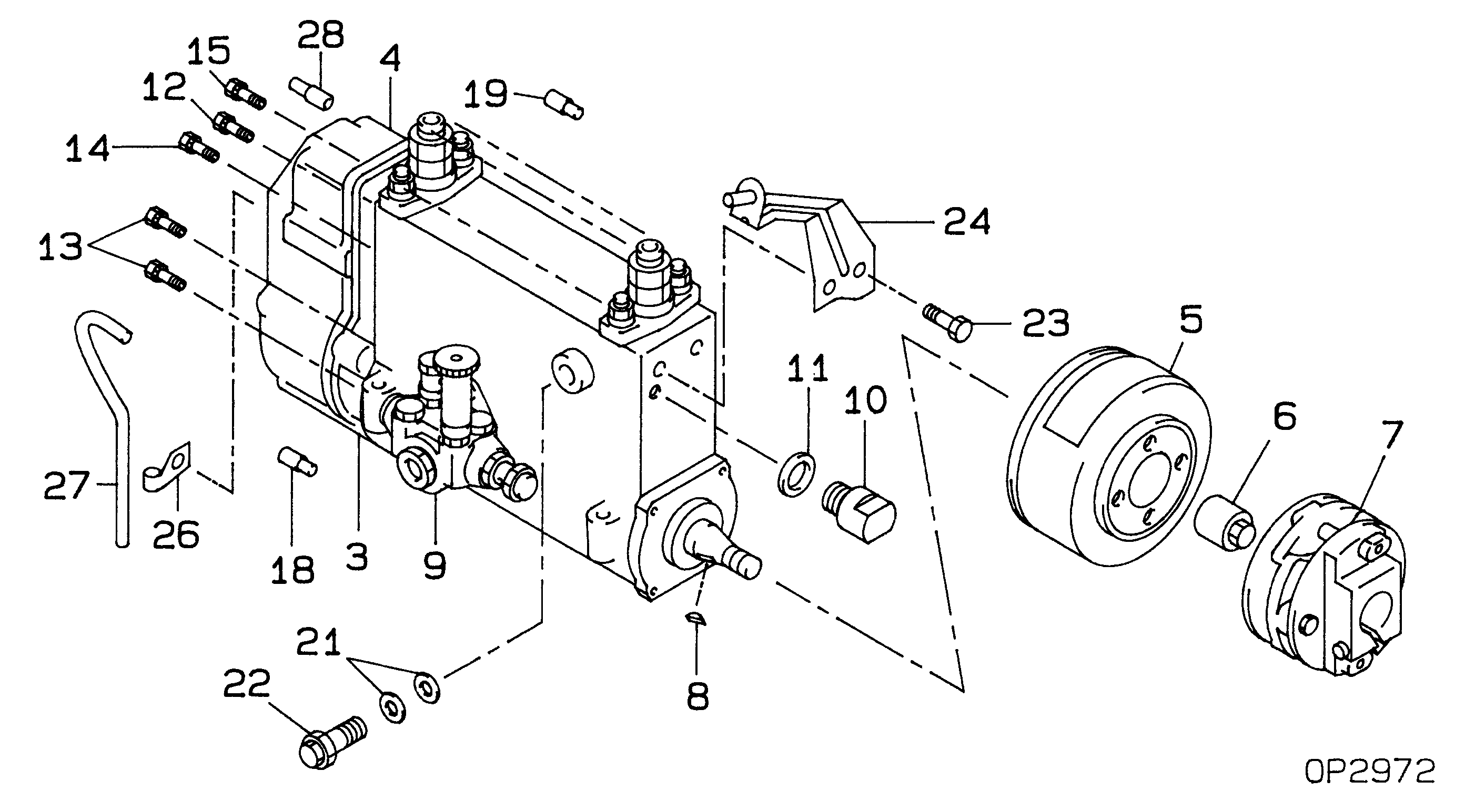
PUMP ASSY, INJECTI
NB6,R901
-0706
22010-8660
HINO
000
[01]
09200-04030
PUMP ASSY, INJECTI
NB6,R901
0706-
S2201-08660-B
HINO
Include in ##:
09200-04030
as PUMP ASSY, INJECTI
09200-04030 PUMP ASSY, INJECTI
Cross reference number
Part num
Firm num
Firm
Name
09200-04030
22010-8660
PUMP ASSY, INJECTI
0920004030
22010-8660
HINO
PUMP ASSY, INJECTI
0920004030
S2201-08660-B
HINO
PUMP ASSY, INJECTI
Information:
2. Loosen bolt (1) until there is approximately 3.18 mm (.125 in) gap between washer (2) and fuel pump drive gear (3).3. Install Tool (C) as shown, and loosen the fuel pump drive gear from the taper on the fuel injection pump camshaft. Remove Tool (C), the bolt, washer and fuel pump drive gear.4. Remove the bolts and plate (4) that hold idler gear (5) in position. Remove the idler gear. If necessary, remove the bearing from the idler gear with Tool (D) and a press.
Do not turn the crankshaft after camshaft gear (6) has been removed. Turning the crankshaft will cause damage to the valves.
5. Remove the four bolts that hold camshaft gear (6) to the camshaft. Remove the camshaft gear.Install Timing Gears
1. Make an alignment of the "C" marks on crankshaft gear (3) and camshaft gear (4). Install the camshaft gear and the bolts that hold it. Tighten the bolts to a torque of 55 7 N m (41 5 lb ft).2. Install the bearing in idler gear (1) with Tool (A). The end of the bearing must be 1.52 mm (.060 in) below the face of the gear hub after installation.3. Be sure the oil hole in the shaft for idler gear (1) is open. Put idler gear (1) and plate (2) in position on the shaft. Install the bolts that hold them. 4. Make sure Tool (C) is in position in the groove of the fuel injection pump camshaft.5. Put fuel injection pump drive gear (5) in position on the fuel injection pump camshaft. Put washer (6) in position on the gear with the largest diameter toward the front of the engine. Install bolt (7), and tighten it to a torque of 7 N m (5 lb ft). Make sure bolt (7) does not turn while the flywheel is being turned.6. Remove the timing bolt from the flywheel, and use Tool (B) to turn the flywheel in the opposite direction of engine rotation. Turn the flywheel until the "C" mark on the crankshaft gear moves 30°.7. Turn the flywheel in the direction of engine rotation until the timing bolt can be installed in the flywheel and the "C" marks are in alignment. This will remove all of the backlash from the timing gears.8. Tighten bolt (7) to a torque of 270 25 N m (199 18 lb ft).9. Remove Tool (B) and (C). Remove the timing bolt from the flywheel. Install the covers on the flywheel housing and fuel injection pump housing. Install the plug in the flywheel housing.End By:a. install timing gear cover