Rating:
Information pump assy, injecti Denso
Product
Fuel Injection Pump
Vehicle engine
INDUSTRIAL 6081A
Engine
6081A
Serial start-end
9509-
Info
Injector Nozzle
093500-6360
Injector nozzle:
0935006360
KIT List:
Part name
Kit1
Kit2
Components :
Scheme #.#:
№
Qty
Part num
Name
Remarks
Manufacture num
000
[01]
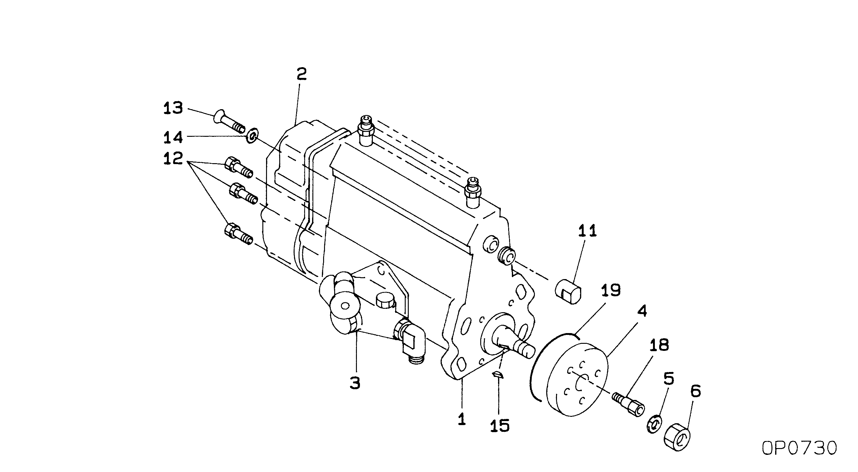
09200-01710
PUMP ASSY, INJECTI
NL6,RSV
Include in ##:
09200-01710
as PUMP ASSY, INJECTI
Cross reference number
Part num
Firm num
Firm
Name
09200-01710
PUMP ASSY, INJECTI
Information:
Fig. 1-Fuel Pump LocationThe fuel transfer pump is located on the right side of the engine as shown on (1, Fig. 1).Removal
Disconnect and plug fuel lines (2, Fig. 1) at pump.Remove attaching hardware.Repair
Airtex Fuel Transfer Pumps
Fig. 2-Airtex Fuel Transfer PumpTo remove or install primer lever, (1, Fig. 2) compress rocker arm lever (2). And pull primer lever out.Further disassembly of the transfer pump is not possible.A.C. Fuel Transfer Pumps
When disassembling, mark pump cover and pump body for easier reassembly.Test all parts for serviceability and replace, if necessary.When assembling the fuel pump, observe the following:
Fig. 3-A.C. Fuel Transfer PumpMake sure diaphragm (1, Fig. 3) is engaged in rocker arm (2).Before installing the pump cover (3), position diaphragm so that it is level by moving rocker arm. Hold lever in this position.Install pump cover and cover screws. However, turn in screws so that they just contact the washers. Operate rocker arm several times, then release with a snap to make sure that diaphragm will not be overstretched when in use. Tighten cover screws in a crosswise pattern.Corona (B.C.D.) Fuel Transfer Pump
When disassembling, mark pump cover and pump body for easier reassembly.
Fig. 4-Diaphragm RemovalDisconnect diaphragm by pressing it against flange (Fig. 4).
Fig. 5-Remove Valve Plate and FilterCarefully remove valve plate with filter from pump cover (Fig. 5).Check all parts for serviceability and replace, if necessary.When assembling the fuel pump, observe the following: Make sure diaphragm is engaged in rocker arm.Before installing the pump cover, position diaphragm so that it is level by moving rocker arm. Hold lever in this position.Install pump cover and cover screws. However, turn in screws so that they just contact the washers.Operate rocker arm several times, then release with a snap to make sure that diaphragm will not be overstretched when in use.Tighten cover screws in a crosswise pattern.Installation
Using a new gasket, attach transfer pump to cylinder block. Connect lines and bleed fuel system.