Rating:
Information pump assy, injecti Denso
Product
Fuel Injection Pump
Vehicle engine
TRUCK D6A210
Engine
D6A210
Serial start-end
9507-
Info
Injector Nozzle
093500-6130
Injector nozzle:
0935006130
KIT List:
Part name
Kit1
Kit2
Components :
Scheme #.#:
№
Qty
Part num
Name
Remarks
Manufacture num
Cross reference number
Part num
Firm num
Firm
Name
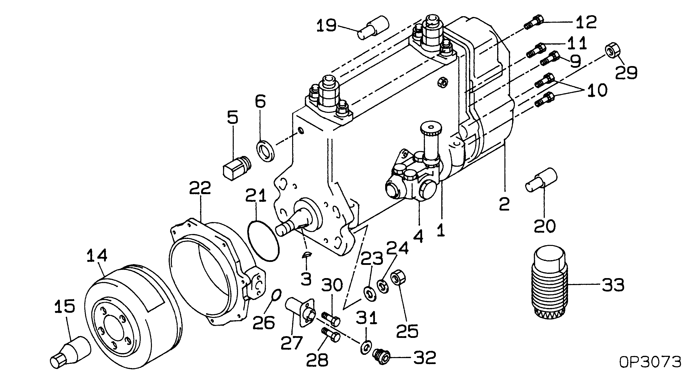
09200-01330
PUMP ASSY, INJECTI
Information:
Typical Example1. Loosen two bolts (2) and two nuts (3). Remove bolt (1), and remove fan drive belts (4).
Typical Example2. Remove the nuts and bolts that hold the fan drive in place. Remove fan drive (5). The following steps are for installation of the fan drive.3. Put fan drive (5) in position on the timing gear cover.4. Install bolts (2) and nuts (3) loosely. Make a replacement of the belts as a set only.5. Install fan belts (4). Install bolt (1). Make an adjustment to the belt tension with tool (A). Measure the belt farthest away from the engine. Tighten new belts to a gauge indication of 120 5. After the engine is operated at high idle for a minimum of 30 minutes, make another adjustment to the belt tension. The correct tension for used belts is a gauge indication of 90 10.6. Tighten bolts (2) and nuts (3) that hold the fan drive in place.Disassemble Fan Drive
Start By:a. remove fan drive 1. Remove two bolts (2) that hold the fan adapter to the pulley.2. Remove fan adapter (1) from the pulley 3. Remove bolts (3) and washer (4). Remove seal (5). 4. Remove pulley (8) from bracket (6).5. Remove bearing (10) and spacer (9) from the pulley. Remove spacer (7), seal (11) and bearing (12) from the pulley.Assemble Fan Drive
1. Install bearing (12) in the rear of pulley (8). 2. Install lip-type seal (11) with tooling (A). The lip of the seal must be away from the bearing. Put 5P960 Multipurpose Type Grease on the lip of the seal.3. Install spacer (7) so the end with the taper is toward the inside of pulley (8).4. Install spacer (9) and bearing (4) in the front of the pulley. 5. Put seal (5) on the front of the pulley. Install the pulley on bracket (6). 6. Install washer (4) and bolts (3) that hold the pulley in position.7. Install the fan drive adapter on the pulley.8. Fill the fan drive with 5P960 Multipurpose Type Grease.End By:a. install fan drive