Rating:
Information pump assy, injecti Denso
Product
Fuel Injection Pump
Vehicle engine
TRUCK D6A180
Engine
D6A180
Serial start-end
9507-
Info
Injector Nozzle
093500-6130
Injector nozzle:
0935006130
KIT List:
Part name
Kit1
Kit2
Components :
Scheme #.#:
№
Qty
Part num
Name
Remarks
Manufacture num
Cross reference number
Part num
Firm num
Firm
Name
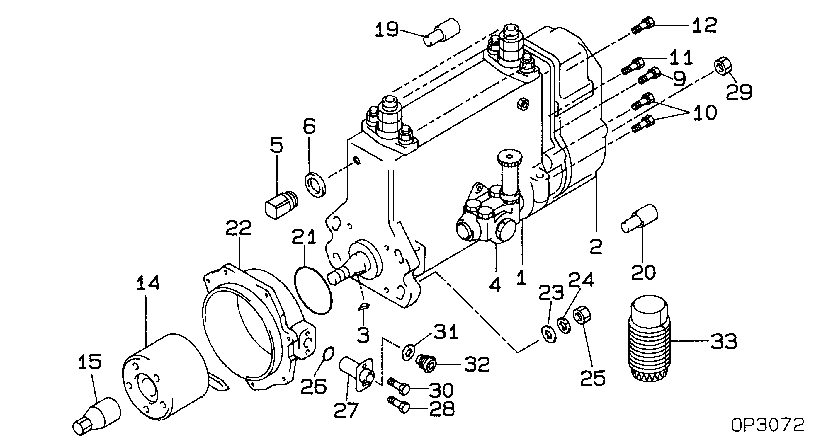
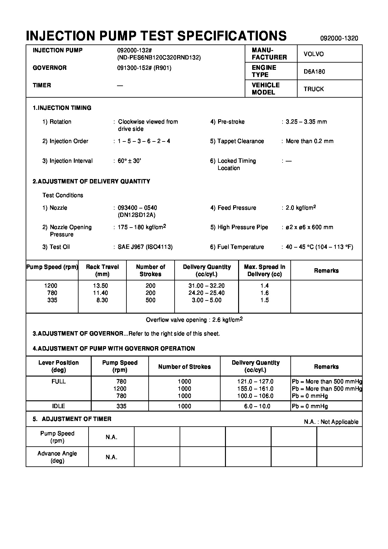
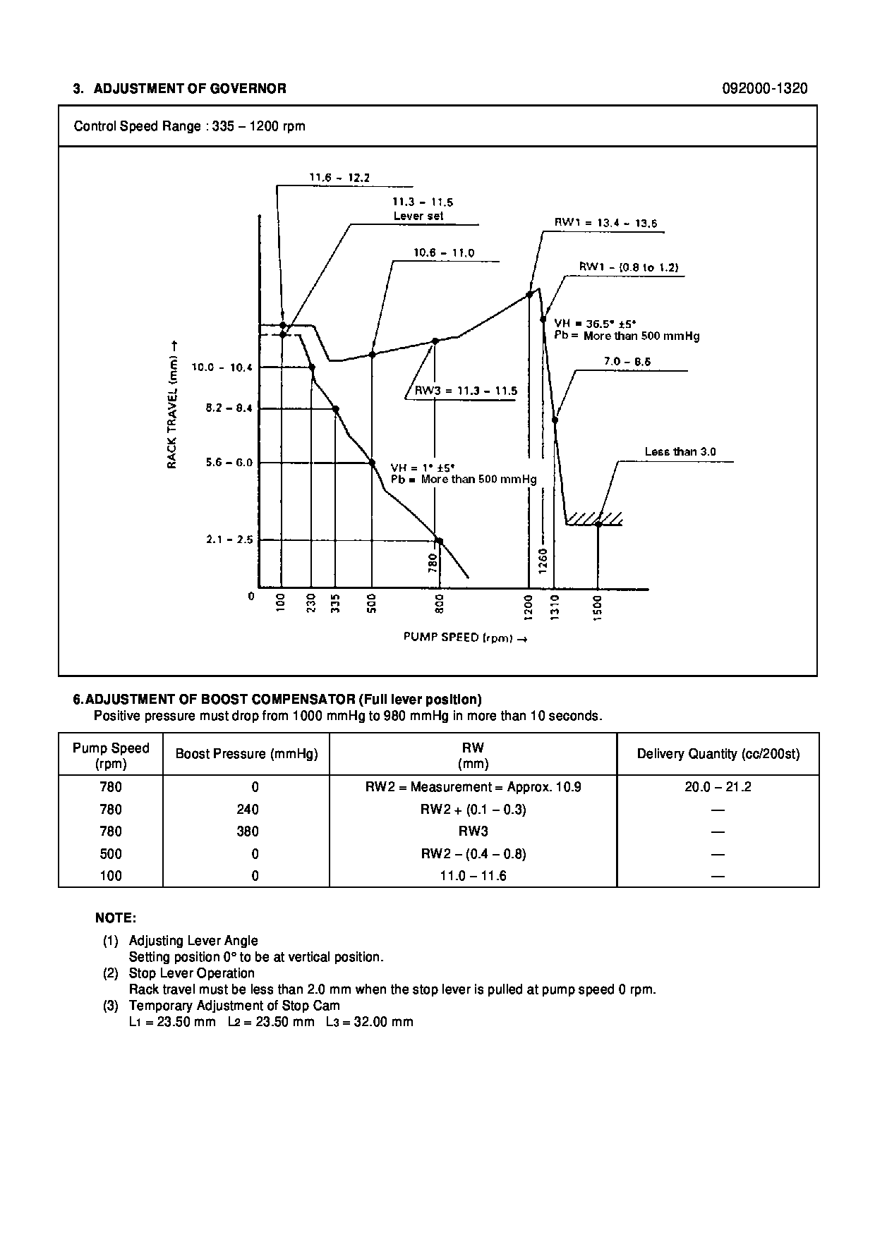
09200-01320
PUMP ASSY, INJECTI
Information:
Typical Example3. Loosen the clamps on breather tube (1), and pull it back for clearance. 4. Remove bolt (2) from the cover on the side of the cylinder block. 5. Remove the three bolts that hold cover (3) to the water pump. Remove cover (3) from the water pump. 6. Remove the two bolts, and remove elbow (4) from bonnet (5). Remove the two bolts, and remove bonnet (5) from the water pump. It is not necessary to remove bolts (6). These bolts only hold the cover to the timing gear cover.7. Remove six long bolts (7) that hold the water pump to the timing gear cover. Remove water pump (8).Install Water Pump
1. Check the O-ring seals and gaskets, and make replacements if needed. 2. Make sure O-ring seal (9) is in position on the water pump. Put water pump (8) into position in the timing gear cover. Install the bolts that hold the water pump in place. 3. Make sure the gaskets are in place. Connect bonnet (5) to the water pump. Connect elbow (4) to the bonnet. 4. Make sure O-ring seal (10) is in position, and install cover (3) on the water pump. 5. Install bolt (2) on the cover on the side of the engine. 6. Put breather tube (1) in position, and install the clamps that hold it.7. Install the altenator mounting group and alternator on the engine.8. Install the water temperature regulator and manifold. See the topic Install Water Temperature Regulator and Manifold.9. Fill the cooling system to the correct level. See the Maintenance Manual.Disassemble & Assemble Water Pump
Start By:a. remove water pump The water pump seal can be replaced without removing the water pump from the engine.An intermittent leakage of a small amount of coolant from the hole in the water pump housing is not an indication of a water pump seal failure. This is required to provide lubrication for the seal. Replace the water pump seal only if a large amount of leakage or a constant flow of coolant is observed draining from the water pump housing. 1. Remove O-ring seal (3) from adapter (4). Remove the adapter from housing (7). Remove the O-ring seal from the outside of the adapter.2. Remove bolt (1) and washer (2). Use tooling (A) to remove impeller (6) from shaft (13).3. Remove spring and seal (5) from the shaft.4. Remove four bolts (16) from retainer (12) that hold the shaft assembly to the pump housing. Remove O-ring seal (18) from housing (7).5. Remove gear and shaft assembly (17) from the housing. Remove bolt (15), retainer (14), and retainer (12) from the shaft assembly.6. Use a press to remove shaft (13) from the gear. Remove bearing (9), spacer (10), and bearing (11) from the shaft.7. Remove lip-type seal (8) from the housing.8. Turn the housing over, and remove ceramic ring (20) and seal (19) from the housing. The following steps are for the assembly of the water pump.9. Use 6V1541 Quick Cure Primer and clean