Rating:
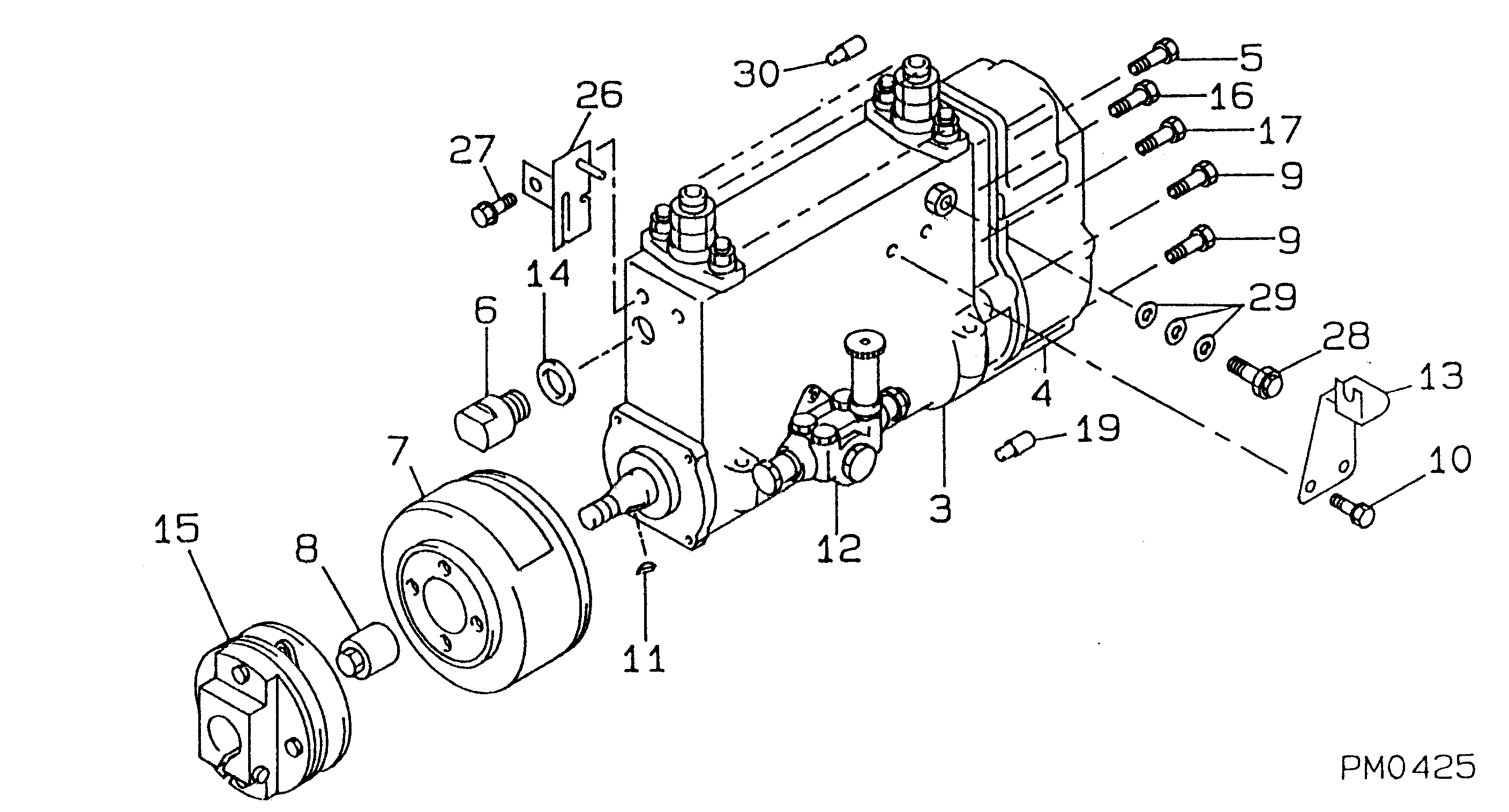
Information pump assy, injecti Denso
Components :
Scheme #.#:
№
Qty
Part num
Name
Remarks
Manufacture num
000
[01]
09200-00121
PUMP ASSY, INJECTI
NB6,R901
9307-
22010-7170
HINO
Include in ##:
09200-00121
as PUMP ASSY, INJECTI
Cross reference number
Part num
Firm num
Firm
Name
09200-00121
22010-7170
PUMP ASSY, INJECTI
Test Calibration Data:
0920000120
22010-7170
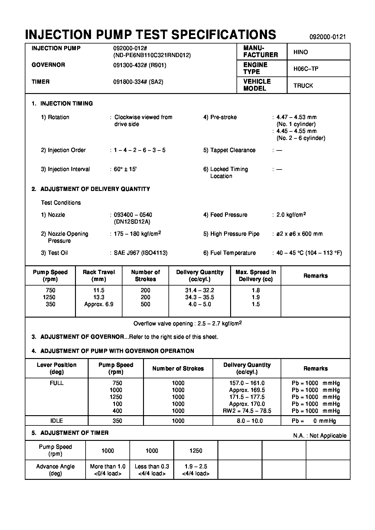
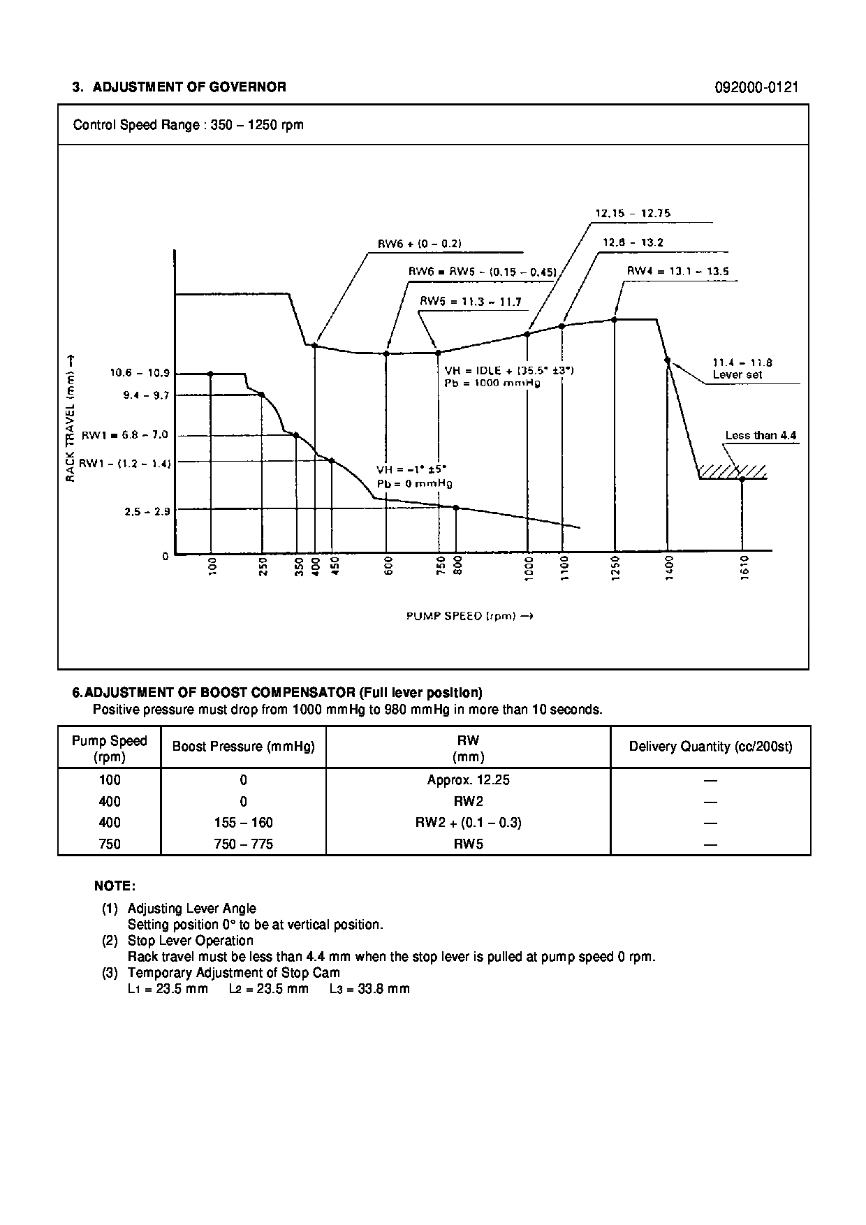
0920000121
22010-7170
Information:
Introduction
The problem that is identified below has a known solution. Use the solution that is identified below.Problem
Excessive white or blue smoke has been observed coming from the exhaust pipe when running the machines listed above at high idle. Running machines at higher altitudes may cause excess fuel burn and excessive smoking.Solution
Sometimes diesel injector timing can be adjusted to eliminate diesel engine smoking. Refer to the procedure below to adjust the injector timing.
Do not operate or work on this product unless you have read and understood the instruction and warnings in the relevant Operation and Maintenance Manuals and relevant service literature. Failure to follow the instructions or heed the warnings could result in injury or death. Proper care is your responsibility.
Personal injury or death may result from failure to adhere to the following procedures.Fuel leaked or spilled onto hot surfaces or electrical components can cause a fire.Clean up all leaked or spilled fuel. Do not smoke while working on the fuel system.Turn the disconnect switch OFF or disconnect the battery when changing fuel filters.
Care must be taken to ensure that fluids are contained during performance of inspection, maintenance, testing, adjusting, and repair of the product. Be prepared to collect the fluid with suitable containers before opening any compartment or disassembling any component containing fluids.Refer to Special Publication, PERJ1017, "Dealer Service Tool Catalog" for tools and supplies suitable to collect and contain fluids on Cat® products.Dispose of all fluids according to local regulations and mandates.
Required Parts
Table 1
Required Parts
Item Qty Part Number Part Name
1 6 562-0435 O-Ring Seal Required Tools
Table 2
Required Tools
Item Qty Part Number Part Name
T1 1 563-4353 Adjustment Tool
T1a 1 - Eccentric Gasket
T1b 1 - Supply Fitting
T1c 1 - Purge Hose
T2 1 - Inlet Hose Diesel Injector Timing Adjustment
Note: The drive clutch side of the engine is cylinder (1), the center is cylinder (2), and the alternator side is cylinder (3).
Remove the valve cover and the fuel rail.
Illustration 1 g06542022
(T1) 563-4353 Adjustment Tool
Illustration 2 g06542023
(T1a) Eccentric gasket
Install adjustment tool (T1) on the injector for center cylinder (2) using eccentric gasket (T1a). Install eccentric gasket (T1a) over the check valve in place of the O-ring.
Illustration 3 g06542029
(T1b) Supply fitting
(T1c) Purge hose
(T2) Inlet hose
Connect a suitable container filled with clean diesel fuel to supply fitting (T1b) using inlet hose (T2). Place a small cup under purge hose (T1c).
Illustration 4 g06536094
(1) Drive clutch side cylinder
(2) Center cylinder
(3) Alternator side cylinder
(A) TDC index mark
Rotate the engine in the direction of rotation (clockwise) until center cylinder (2) is at Top-Dead-Center (TDC) with the compression stroke. The reference mark for center cylinder (2) must be aligned with the TDC index mark (A) and the valves must be closed.