Rating:
Information pump elements Denso
Compare Prices: .
As an associate, we earn commssions on qualifying purchases through the links below

$46.25
17 May 2024
CN: Diesel Injection Par
Cabezales A38 Fuel Injection Plunger Barrel Assembly 131151-2220 9413610047 Fit for Mitsubishi Fuso 6D14 6D140A Engine 6Pcs/Lot
Cabezales Manufacturer MFR Number:131151-2220 , 9413610047 , ME704103 Stamping No.: A38 || Package: 6 pieces of plunger and barrel.Neutral packing. || Application:Fit for Mitsubishi Fuso 6D14 6D140A Engine . || Premium Quality:Our plungers and barrels made of premium strength metal and composite plastic.we have a good air and fuel mixing ability and excellent ability of fuel pump systems,and plunger assembly be inspected reliability and durability in the factory. || Notice:Please you carefully check your vehicle plunger barrel and make sure that the number must be completely the same as our description fitment,if you have any problem,please you contact us by email,we will have professional customer service within 24 hours.
Cabezales Manufacturer MFR Number:131151-2220 , 9413610047 , ME704103 Stamping No.: A38 || Package: 6 pieces of plunger and barrel.Neutral packing. || Application:Fit for Mitsubishi Fuso 6D14 6D140A Engine . || Premium Quality:Our plungers and barrels made of premium strength metal and composite plastic.we have a good air and fuel mixing ability and excellent ability of fuel pump systems,and plunger assembly be inspected reliability and durability in the factory. || Notice:Please you carefully check your vehicle plunger barrel and make sure that the number must be completely the same as our description fitment,if you have any problem,please you contact us by email,we will have professional customer service within 24 hours.

$90.44
04 Jul 2024
0.1102[0.05] pounds
CN: CHENG2568MALL
NAttco Diesel Fuel Pump A38 Plunger 131151-2220, CHENG2568MALL
NAttco The pump plunger should choose the appropriate material according to the specific application to adapt to different media and working conditions. || The size and shape of the pump plunger is also limited by the size and type of pump. || The design of the car plunger should take into account the gap between the piston and the cylinder to ensure the sealing effect and smooth movement. || The diameter and travel of the plunger determine the displacement of the engine. || Automotive plungers usually have a raised top, called the piston head or piston top.
NAttco The pump plunger should choose the appropriate material according to the specific application to adapt to different media and working conditions. || The size and shape of the pump plunger is also limited by the size and type of pump. || The design of the car plunger should take into account the gap between the piston and the cylinder to ensure the sealing effect and smooth movement. || The diameter and travel of the plunger determine the displacement of the engine. || Automotive plungers usually have a raised top, called the piston head or piston top.

$66.49
20 Jul 2024
KR: Adabus
131151-2220 diesel pump plunger A38
Generic Placement on vehicle: Fuel injection pump || Country/region of manufacture: China || Material type: iron || Item weight: 0.5KG
Generic Placement on vehicle: Fuel injection pump || Country/region of manufacture: China || Material type: iron || Item weight: 0.5KG
Include in ##:
Number on scheme 010

09010-03351
as ELEMENT SUB-ASSY,
Cross reference number
Part num
Firm num
Firm
Name
090150-1820
131151-2220
ZEXEL
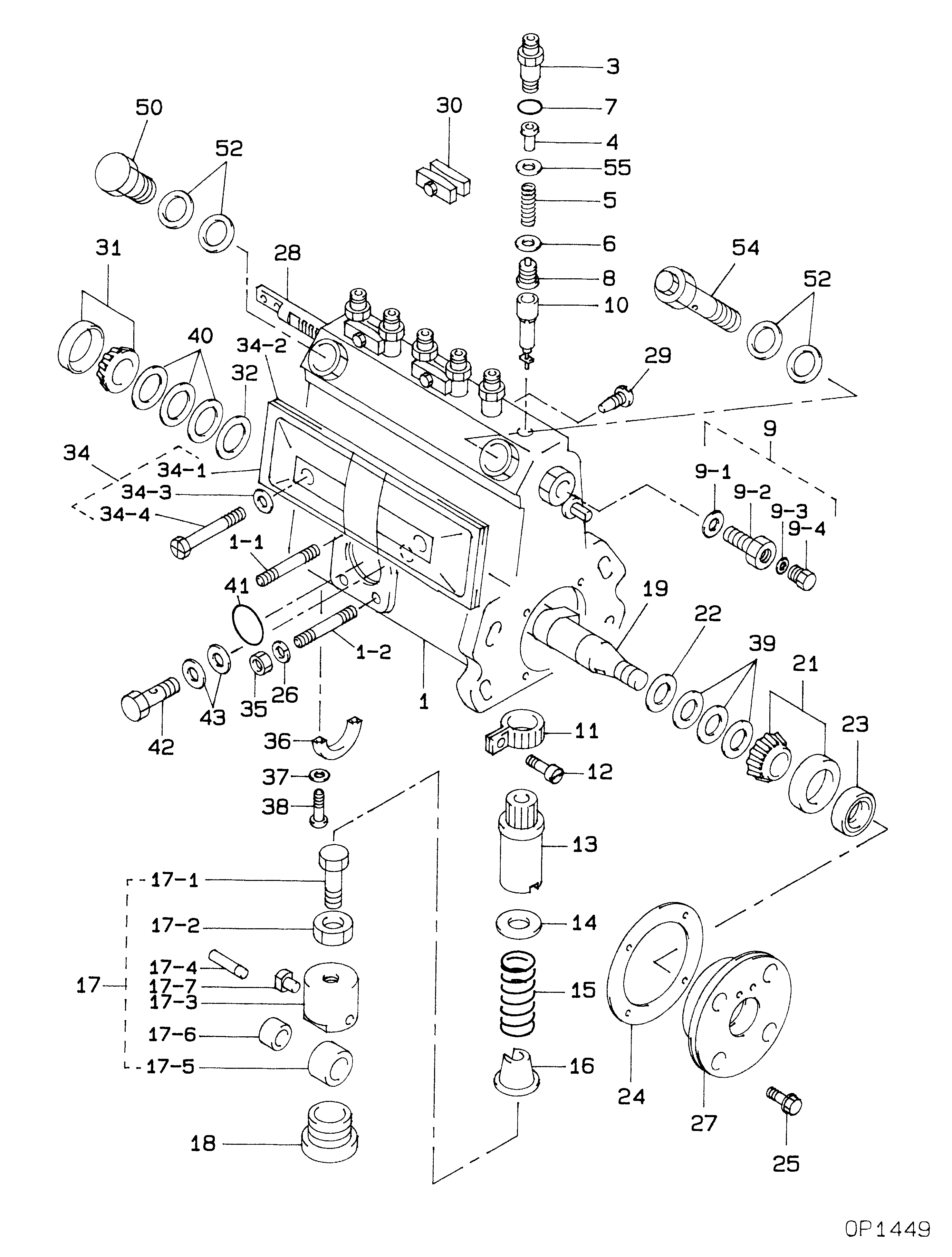
PUMP ELEMENTS
Information:
Introduction
Do not perform any procedure in this Special Instruction until you have read the information and you understand the information.Removing the Fuel Injection Pump
Remove the counterweight from the machine.
Shut off the disconnect switch for the main power.
Manually crank the engine until the No. 1 piston is at the top center on the compression stroke.
Illustration 1 g01400895
Disconnect the fuel inlet and the fuel return hoses (9) from the fuel injection pump.
Remove the fuel hose from the transfer pump to the priming pump (4) .
Remove the fuel hose from the filter to the fuel injection pump (1) .
Remove the tubes to the injector and remove the clamps (2) .
Remove the pipe for the fuel return and the clamps (3) .
Remove the oil tube for lubrication from fuel injection pump (10). Plug the ports with 5I-7505 Plug .
Remove the oil tube for lubrication from timing gear cover (8). Plug the empty ports with 5I-7505 Plug .
Disconnect the shut off solenoid. Remove the shut off solenoid and remove the connection rod from the fuel injection pump (12) .
Remove the timing gear cover (5), the cover, the bolts and washers. The components will be reinstalled.
Remove the bracket for the fuel injection pump (11) .
Remove the fuel injection pump (6) .
Illustration 2 g01400940
Loosen the connector for the governor cable (13). Disconnect the cable from the lever.
Remove the spring and remove the bracket (14) .
Remove the governor lever (15) .
Illustration 3 g01400950
Loosen nuts (17). Remove the cable for the governor from the bracket.
Remove bracket (16) .
Illustration 4 g01400963
Remove clip (18) .
Remove the clip and bracket (19). Do not discard the components.
Illustration 5 g01400997
Illustration 6 g01401000
Detail A
Remove bolt (20). Remove bracket (21) .
Cut strap (22). Remove the harness.
Illustration 7 g01401009
Detail B
Disconnect the harness from shut off solenoid (23). Remove the harness.Installing the new Rotary Fuel Injection Pump
Illustration 8 g01401319
(24) 306-2165 Pump Flange (25) 306-2160 Rotary Fuel Injection Pump
Mount the rotary fuel injection pump (25) on the flange (24) with 294-5060 O-Ring Seal , 234-4835 Studs and 244-7127 Flange Nuts .
Illustration 9 g01401330
(26) 306-2164 Rotary fuel Injection Pump Gear (27) 294-7251 Bolt (28) 300-3988 O-Ring Seal
Mount gear (26) on the pump shaft.Note: Ensure that the two "3's" on the rotary fuel injection pump gear straddle a tooth on the idler gear. The "3's" do not need to straddle the "3" on the idler gear.
Install the rotary fuel injection pump and flange assembly. Use bolt (27) and O-ring (28) in order to install the rotary fuel injection pump and the flange assembly.
Illustration 10 g01401333
(31) 212-8510 Nut (32) 199-2354 Bolt (33) 6V-6317 Bolt (34) 6V-5839 Washer (35) 235-4970 Bolt (36) 300-3867 Washer (37) 225-52