Rating:
Information pump assy, injecti Denso
Product
Fuel Injection Pump
Vehicle engine
INDUSTRIAL H
Engine
H
Serial start-end
7209--8809
Info
Injector Nozzle
093500-0910
Injector nozzle:
0935000910
KIT List:
Components :
Scheme #.#:
№
Qty
Part num
Name
Remarks
Manufacture num
Cross reference number
Part num
Firm num
Firm
Name
09000-06480
PUMP ASSY, INJECTI
0900006480
25800-30201-71
TOYOTA
PUMP ASSY, INJECTI


Information:
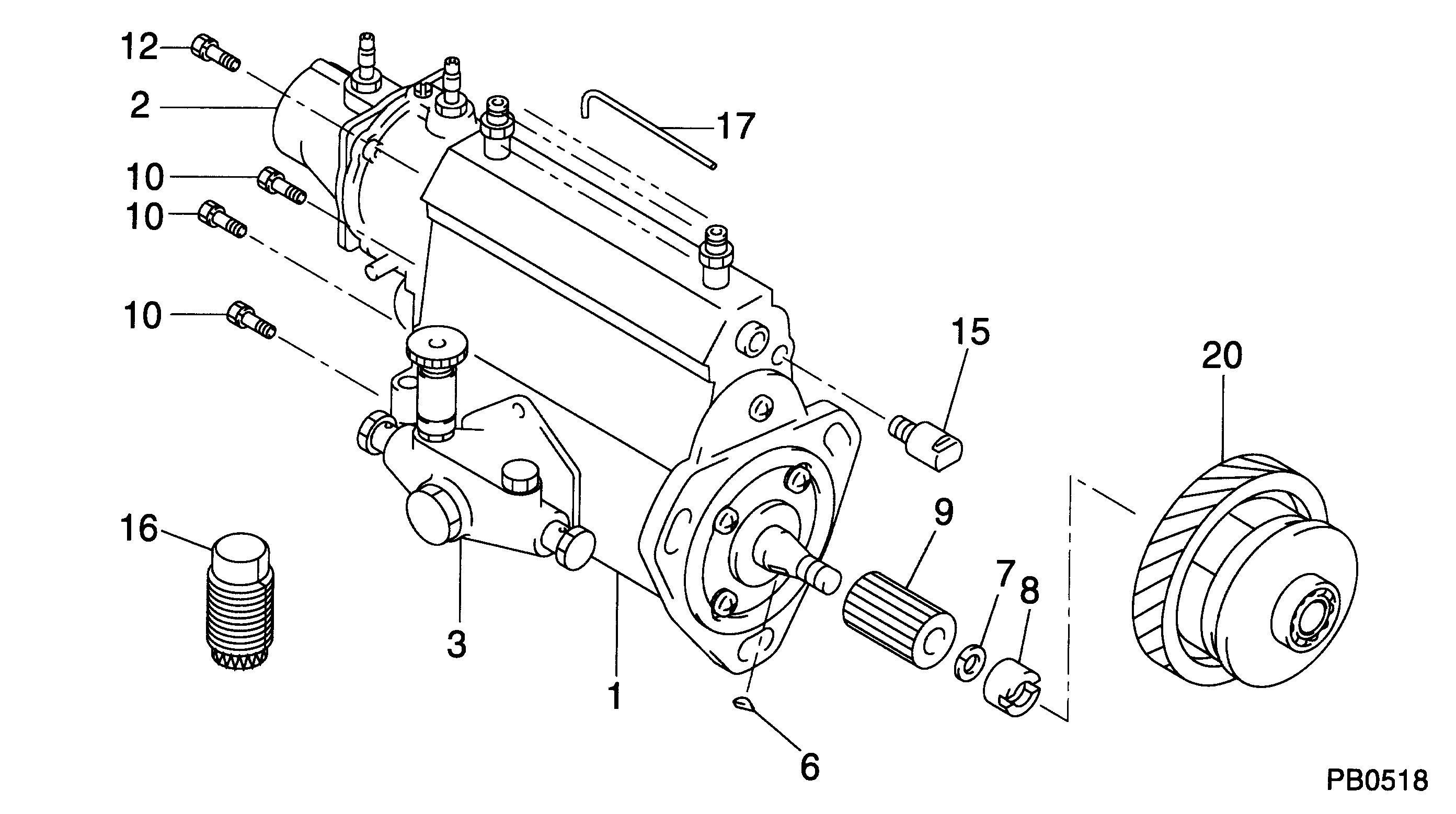
Start By:a remove rack actuator packageb. remove fuel injection pumps 1. Remove rack (1) from the fuel pump housing. 2. Remove six lifters (2) from the fuel pump housing. Put identification marks on the lifters for installation purposes. 3. Remove camshaft (3) from the fuel pump housing. It may be necessary to use a soft hammer to push the camshaft out of the governor end of the fuel pump housing. 4. Remove races (4) and bearing (5) from the camshaft. Remove ring (6) if necessary. 5. Remove rack bearing (7) from both ends of the housing and dowel (8) if necessary. 6. Use tooling (A), and remove three camshaft bearings (9). 7. Remove the bolts, cover (10) and the gasket. 8. Remove pins (12), the seal and dowels (11) if necessary. Pins (12) must be pushed from the inside out.Assemble Fuel Injection Pump Housing
1. Clean and inspect all parts. Make a replacement of all parts that are worn or damaged. 2. Lubricate the seal with clean engine oil, and install pin (12). Pin (12) must protrude into the pump bore 2.15 .05 mm (0.85 .002 in.).3. Install dowel (11) so that it protrudes into the pump bore 1.93 .05 mm (0.76 .002 in.). 4. Install the gasket, cover (10) and the bolts. 5. Install the rack bearing with tooling (B). Install the bearing until the driver comes in contact with the plate. The bearing should be installed to a depth of 83.0 0.5 mm (3.27 .02 in.) from the fuel pump mounting face. 6. Measure the rack bearing (7). Dimension (X) must be 11.178 0.05 mm (.4400 .002 in.). Dimension (W) must be 12.767 0.058 mm (.5026 .0022 in.). 7. Install dowel (8). Dowel (8) must protrude 6.0 0.5 mm (.24 .02 in.) from the fuel pump housing face.8. Install the rear rack bearing with tooling (C) to a depth of 7.16 0.13 mm (.282 .005 in.) below the fuel pump housing surface. The inside diameter of the rear rack bearing must be 12.746 0.045 mm (.5018 .0017 in.). 9. User tooling (D), and install three camshaft bearings (9). Oil holes (13) in the camshaft bearings must be positioned 30° 3° above the horizontal centerline toward the engine side of the fuel pump housing. The outer bearings must be installed 1.0 0.5 mm (0.04 0.02 in.) below the surface marked (Z). The inner bearing must be installed 218.0 0.3 mm (8.58 .012 in.) below the front surface (Y). Diameter (XX) must be 68.339 0.038 mm (2.6905 0.015 in.) after assembly. 10. Install ring (6) races (4) and bearing (5) on the camshaft. 11. Lubricate can bearings (9) and cam shaft bearing journals with clean engine oil.12. Install camshaft (3) into the fuel pump housing.
The notch on the lifter must be in line with the dowel in the lifter bore. The lifter must slide up and