Rating:
Information pump assy, injecti Denso
Product
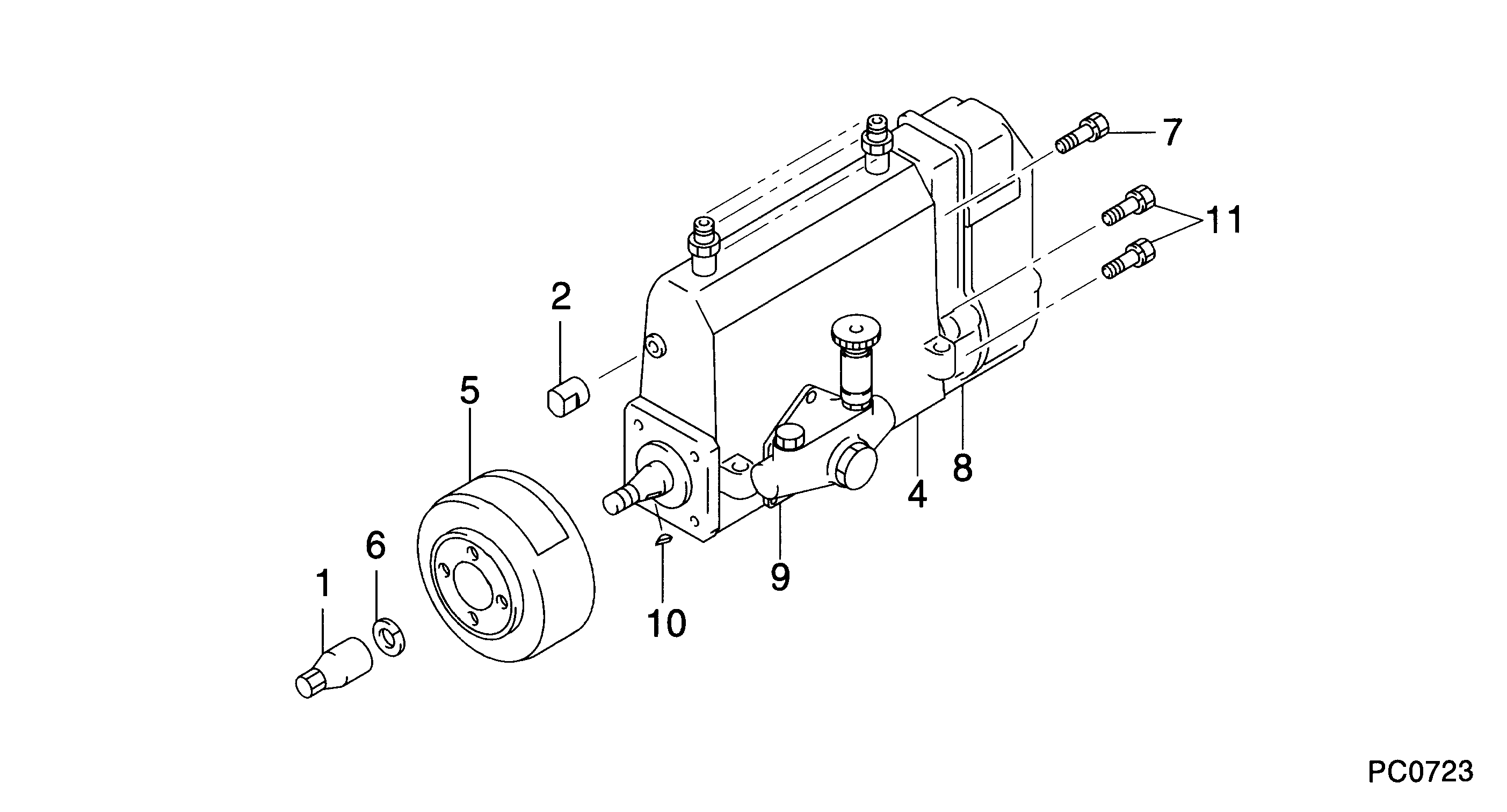
Fuel Injection Pump
Vehicle engine
INDUSTRIAL 6DS50A
Engine
6DS50A
Serial start-end
7101--7104
Info
Injector Nozzle
093500-0550
Injector nozzle:
0935000550
KIT List:
Components :
Scheme #.#:
№
Qty
Part num
Name
Remarks
Manufacture num
Cross reference number
Part num
Firm num
Firm
Name
09000-04330
PUMP ASSY, INJECTI


Information:
Installation:
A. Remove The Failed Harness
1. Remove the section of failed harness:2. Locate the IAPCV at the inboard rear and top of the high pressure hydraulic pump. The pump is mounted to the back of the front cover on the upper left side of the engine, as seen from the driver's seat, (illustration 1 and 2).3. Gently pry open the "ears" (illustration 4), that retain the 2-pin electrical connector in place, and unplug the harness from the 122-5053 IAPCV.4. Remove the harness tie wraps from the IAPCV back to connector P2. There is one tie a few inches below the connector (illustration 1 and 2), and two more along the engine block toward the rear.
Illustration 1. High pressure hydraulic pump (1), 2-pin Packard Electrical Connector (2), tie wraps (3), 40-pin connector P2 (4), 40-pin connector J2 (5).
Illustration 2. Hydraulic pump (6), IAPCV (7), tie wrap (8), Fuel Transfer Pump Gp (9).5. On early production engines the 122-8835 Wiring Harness is one piece. If so, cut the IAPCV Sensor Wires where they emerge from the braid at the sensor end. On later engines, the harness has four separate sections.6. Remove the 40-pin connector P2 from J2 on the ECM by unscrewing the M5 Allen Head Screw from the rear of J2.7. Using the 121-9588 Deutsch Pin Removal Tool (medium blue, for #16 and #18 gauge wires), remove the two pins from P2 (illustration 3). Insert wire removal tool without twisting.8. Remove the pink wire from P2 pin-19 and the black wire from P2 Pin-13. Cut these two wires where they emerge from the braid near P2.B. Install New 122-8842 Wiring Harness:
Illustration 3. P2 pin-13 (1), P2 pin-19 (2), P2 harness side of 40-pin connector (3), J2 ECM side of 40-pin connector (4), M5 Allen Head Screw (5).1. Install harness in reverse order of removal. Begin by inserting the pink wire pin into P2 pin-19 and black wire pin into P2 pin-13. After inserting, use the 45 N (10 lb) pull test, to verify that the connection is secure.2. Blend the two wires from the replacement harness in with all the other wires coming from P2 and install a tie wrap about three inches from P2.3. Route the replacement IAPCV Harness along with the old harness (which still contains the two twisted pairs going to the Speed Timing Sensors) until forward of the second secured tie wrap. Be sure the wires are routed next to the block, between the block and the oil feed tube to the hydraulic oil pump.4. Use tie wraps to bind the replacement harness to the old harness. Be sure new tie wraps are installed around both harnesses in the three locations that are secured to the block. Use as many additional unsecured tie wraps as necessary to bind the two harness sections tightly together. Do not attach tie wraps to individual wires. Attach only to braided sections of harness.
It is especially important to replace the tie wrap nearest the sensors, to prevent sensor failure caused by