Rating:
Information piston assy, timer Denso
Include in ##:
Number on scheme 041

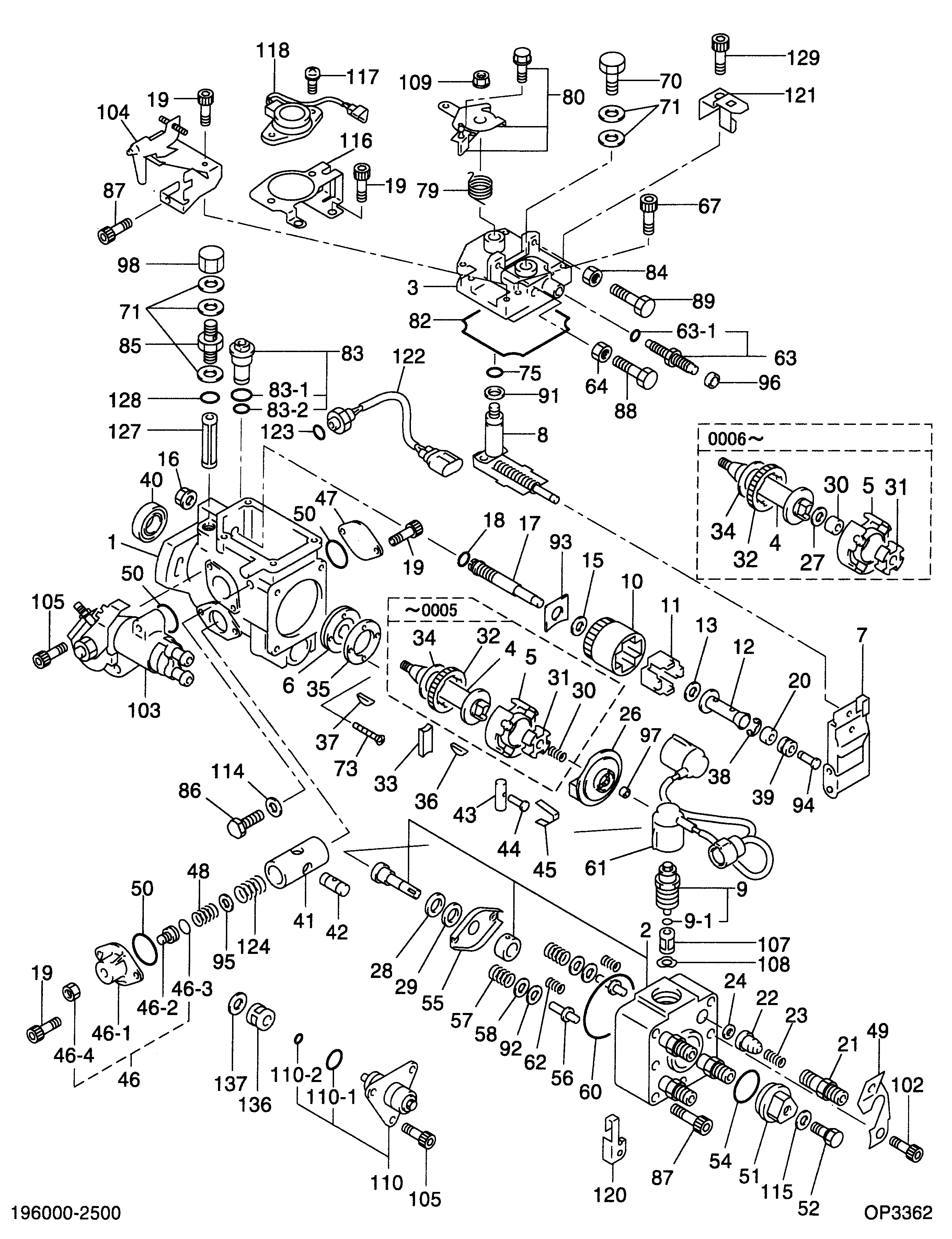
19600-02501
as PISTON ASSY, TIMER
Cross reference number
Part num
Firm num
Firm
Name
09619-01490
22582-5B82
PISTON ASSY, TIMER
0961901490
22582-5B820
TOYOTA
PISTON ASSY, TIMER
0961901490
ME743591
MITSUBISHI
PISTON ASSY, TIMER
Information:
3. With dial indicator set at "0" (zero) at location (A), turn the crankshaft and read the indicator at locations (B), (C) and (D).4. The difference between lower and higher measurements taken at all four points must not be more than 0.20 mm (.008 in.)Bore Runout
Write the dial indicator measurements with their positive (+) and negative (-) notation (signs). This notation is necessary when the calculations are made in the chart correctly. 1. Fasten a dial indicator to the crankshaft flange so the 7H1940 Universal Attachment of the indicator is in contact with the inner flywheel housing bore at location (C). Adjust the dial indicator to "0" (zero). Push the crankshaft up against the top crankshaft bearing. Write the measurement for bearing clearance on line 1 in column (C) of the chart.2. Divide the measurement from Step 1 by 2. Write this number on line in columns (B) and (D). 3. Turn the crankshaft to put the dial indicator at (A). Adjust the dial indicator to "0" (zero).4. Turn the crankshaft counterclockwise to put the dial indicator at (B). Write the measurement in the chart.5. Turn the crankshaft counterclockwise to put the dial indicator at (C). Write the measurement in the chart.6. Turn the crankshaft counterclockwise to put the dial indicator at (D). Write the measurement in the chart.7. Add lines I and II by columns. 8. Subtract the smaller number from the larger number in line II in columns (B) and (D). The result is the horizontal "eccentricity" (out of round). Line III, column (C) is the vertical eccentricity. 9. On the graph for total eccentricity, find the point of intersection of the lines for vertical eccentricity and horizontal eccentricity.10. If the point of intersection is in the range marked "Acceptable" the bore is in alignment. If the point of intersection is in the range marked "Not Acceptable", the flywheel housing must be changed.
Write the dial indicator measurements with their positive (+) and negative (-) notation (signs). This notation is necessary when the calculations are made in the chart correctly. 1. Fasten a dial indicator to the crankshaft flange so the 7H1940 Universal Attachment of the indicator is in contact with the inner flywheel housing bore at location (C). Adjust the dial indicator to "0" (zero). Push the crankshaft up against the top crankshaft bearing. Write the measurement for bearing clearance on line 1 in column (C) of the chart.2. Divide the measurement from Step 1 by 2. Write this number on line in columns (B) and (D). 3. Turn the crankshaft to put the dial indicator at (A). Adjust the dial indicator to "0" (zero).4. Turn the crankshaft counterclockwise to put the dial indicator at (B). Write the measurement in the chart.5. Turn the crankshaft counterclockwise to put the dial indicator at (C). Write the measurement in the chart.6. Turn the crankshaft counterclockwise to put the dial indicator at (D). Write the measurement in the chart.7. Add lines I and II by columns. 8. Subtract the smaller number from the larger number in line II in columns (B) and (D). The result is the horizontal "eccentricity" (out of round). Line III, column (C) is the vertical eccentricity. 9. On the graph for total eccentricity, find the point of intersection of the lines for vertical eccentricity and horizontal eccentricity.10. If the point of intersection is in the range marked "Acceptable" the bore is in alignment. If the point of intersection is in the range marked "Not Acceptable", the flywheel housing must be changed.