Rating:
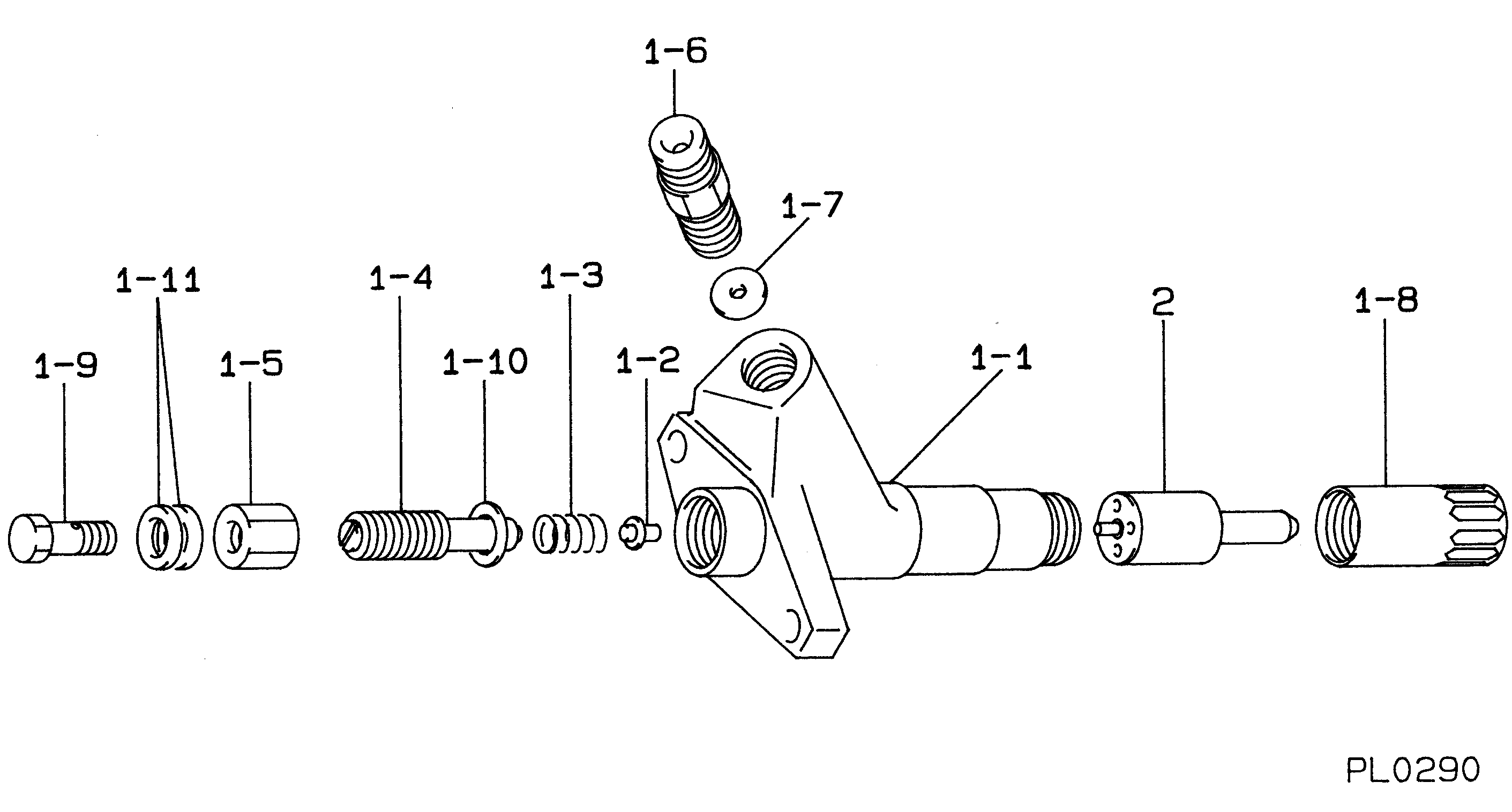
Information nozzle assy Denso
Nozzle Type:
ND-DLLA145SND313
MITSUBISHI INDUSTRIAL 6D16T2
Compare Prices: .
As an associate, we earn commssions on qualifying purchases through the links below

093400-3130 Fuel Injection Nozzle 6Pcs
DFGUFG [Product compatibility]: The OE number of this product is 093400-3130 || [Enhanced Fuel Efficiency & Power Output: Precision-engineered fuel injectors optimize spray patterns for improved combustion efficiency, directly boosting mileage while maintaining stable engine performance across all RPM ranges || [Easy to install and affordable]: Each fuel injector meets factory standard specifications, is simple and convenient to install, has higher combustion efficiency, and can effectively reduce fuel consumption || [High-quality materials for better performance]: The injectors are made of high-quality materials and advanced manufacturing processes to ensure durability and service life, allowing your engine to run smoothly for a long time || [Guaranteed Engine Performance]: This product is one of the key components of electronic fuel injection engines, helping to improve engine performance
DFGUFG [Product compatibility]: The OE number of this product is 093400-3130 || [Enhanced Fuel Efficiency & Power Output: Precision-engineered fuel injectors optimize spray patterns for improved combustion efficiency, directly boosting mileage while maintaining stable engine performance across all RPM ranges || [Easy to install and affordable]: Each fuel injector meets factory standard specifications, is simple and convenient to install, has higher combustion efficiency, and can effectively reduce fuel consumption || [High-quality materials for better performance]: The injectors are made of high-quality materials and advanced manufacturing processes to ensure durability and service life, allowing your engine to run smoothly for a long time || [Guaranteed Engine Performance]: This product is one of the key components of electronic fuel injection engines, helping to improve engine performance

6PCS Diesel Fuel Injector Tips DLLA145SND313 Injectors Nozzle 0934003130 Compatible with Mitsubishi Industrial 6D16T2 ME743161
DICSCL PARCS Part number: 093400-3130 , Stamping No: DLLA145SND313 || Compatible with Mitsubishi Industrial 6D16T2 ME743161 || 100% brand new and high quality Made High-quality steel materia. || Longer Service Life: High quality durability material and excellent crafts, as well as the applied series of tests in RD center before they were listed, provide a reliable operation and longer service life of this item. || 【Notice】: Please check your car information before purchase.
DICSCL PARCS Part number: 093400-3130 , Stamping No: DLLA145SND313 || Compatible with Mitsubishi Industrial 6D16T2 ME743161 || 100% brand new and high quality Made High-quality steel materia. || Longer Service Life: High quality durability material and excellent crafts, as well as the applied series of tests in RD center before they were listed, provide a reliable operation and longer service life of this item. || 【Notice】: Please check your car information before purchase.

4PCS Diesel Fuel Injector Tips DLLA145SND313 Injectors Nozzles 0934003130 Compatible with Mitsubishi Industrial 6D16T2 ME743161
DICSCL PARCS Part number: 093400-3130 , Stamping No: DLLA145SND313 || Compatible with Mitsubishi Industrial 6D16T2 ME743161 || 100% brand new and high quality Made High-quality steel materia. || Longer Service Life: High quality durability material and excellent crafts, as well as the applied series of tests in RD center before they were listed, provide a reliable operation and longer service life of this item. || 【Notice】: Please check your car information before purchase.
DICSCL PARCS Part number: 093400-3130 , Stamping No: DLLA145SND313 || Compatible with Mitsubishi Industrial 6D16T2 ME743161 || 100% brand new and high quality Made High-quality steel materia. || Longer Service Life: High quality durability material and excellent crafts, as well as the applied series of tests in RD center before they were listed, provide a reliable operation and longer service life of this item. || 【Notice】: Please check your car information before purchase.
Include in ##:
Cross reference number
Part num
Firm num
Firm
Name
09340-03130
NOZZLE ASSY
Information:
D11N 74Z1-729Introduction
The Automatic Ether Injection System controls the amount of ether to be injected into the engine intake manifold during cold weather starting. Correct operation of this electronically controlled system is required to prevent possible damage to the engine during cold-start conditions.This instruction gives the procedure needed to install the automatic ether injection system for the engine in a D11N Tractor, within the product identification number range given. Installation of this ether injection system will ensure that the correct amount of ether is injected when ether is required during the starting procedure.Do not perform any procedure, outlined in this publication, or order any parts until you read and understand the information contained within. Before starting the installation procedure, make certain the machine disconnect switch is in the OFF position.Reference: Service Manual, form SENR4705. Necessary Parts
Installation Procedure for Components of Automatic Ether Injection System
If the machine is equipped with an earlier version ether starting aid group, remove the entire system with the exception of the in-cab, dash mounted, 8C9812 Switch and the tubing to the turbocharger outlet adapters. This consists of two nozzles, two tubes from the nozzles to a tee, and the tee.All electrical wiring from the earlier system must also be removed, including the wiring to the 8C9812 Switch.Installation of Components in the Cover Assembly
The cover assembly provides a mounting location and protection for the solenoid valve, ether cylinders, reset switch (and the reset switch bracket), and the electronic control unit (ECU). This complete unit will be mounted toward the rear of the fender, on the left side of the machine. The location will be to the rear of the air conditioner/heater, but forward of the fuel tank.All existing components currently located in this area must be removed and relocated. A section of the skid plate, (the section from the rear edge of the air conditioner/heater to the fuel tank) must be removed. 1. Put four 8C5607 Mounts into the holes provided in each of the two 8E1355 Plates (2). Insert an 8C5608 Spacer into each shock mount. Use 5P2675 Bolts (1) with 9X6165 Washers to fasten the two 8E1355 Plates (2) to plates (3) in the cover assembly.Use a crimping tool to install a 2L8079 Terminal on one end of the 5P5624 Wire, then install a 2L8077 Terminal on the other end.Use one of the bolts to fasten this newly fabricated wire assembly (4) into position [between the upper bolt and washer for one of the plates (2)] as shown.
The ECU and the bolts (5) that retain it are shown here for location purposes only. Installation of the ECU is not to be done until all welding procedures are completed.
2. Install a 5P0598 Clamp through slot (A) of each ether valve assembly mounting plate (6). Remove plug (B) at the bottom of each solenoid valve. 3. Install a 7X1063 Orifice Fitting (7) (left hand thread) in the hole at each location where a plug (B) was removed. Make sure that filter (8) is installed and