Rating:
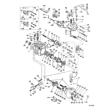
Information lever sub-assy, ad Denso
Include in ##:
09600-01040
as LEVER SUB-ASSY, AD
Cross reference number
Part num
Firm num
Firm
Name
09643-50620
LEVER SUB-ASSY, AD
Information:
Introduction
This Special Instruction provides the necessary information required to disassemble, clean, inspect, and assemble unit injectors for 3600 Engines.This Special Instruction also includes the dimensions and recommended material for fabricating specialized tooling. This Special Instruction should be read and understood before proceeding with any disassembly, cleaning, inspection, or assembly.Unit Injector Components Are Not Serviced
The component parts in unit injectors used for 3600 Engines are NOT serviced.The unit injectors will be OUT of calibration if components are interchanged within the unit injectors.If during the cleaning and inspection procedure a component is found to be excessively worn, the complete unit injector must be REPLACED.Factory Adjustment ONLY
A trim bolt (Allen head design) is provided on the unit injectors to adjust the rack zero point at the factory ONLY.The ALLEN HEAD trim bolt should NOT be moved, adjusted, or tightened.There have been instances where the bolt has been mistaken for a fastener rather than an adjustment.
If the Allen head trim bolt is MOVED, ADJUSTED, or TIGHTENED, low power and an imbalance of fuel flowing into each engine cylinder can result. This can cause unequal power output from each engine cylinder.If the trim bolt is moved, the fuel injector must be completely recalibrated.This calibration is a FACTORY ADJUSTMENT ONLY.
Work Area Environment And Component Cleaning Procedures
The cleanliness of the parts and the work area during this repair procedure is VERY important.The cleaning procedure should be performed in an air-conditioned area to provide humidity control and isolation from contamination in the air.Work surfaces of stainless steel are best.Do NOT use work benches with painted surfaces or those made of materials that are difficult to keep clean.If non-metallic materials are to be used for the work bench tops, the material must be resistant to chipping and scratching, and not affected by diesel fuel, test fluid, or caustic solutions.Recommended Tools
The use of some of the following tools (Ultrasonic Cleaner and Test Fluid) depends on the type of cleaning. Read this Special Instruction before ordering. Fabricated Specialized Tooling
Sleeve (Tool A)
Illustration 1: (A) 100 mm (4.0 in). (B) 77.22 0.05 mm (3.040 .002 in). (C) 75 mm (3.0 in). (D) 54.8 mm (2.16 in). (E) 3 mm (.1 in). (F) 82.68 0.05 mm (3.255 .002 in). (G) 1.5 mm (.06
