Rating:
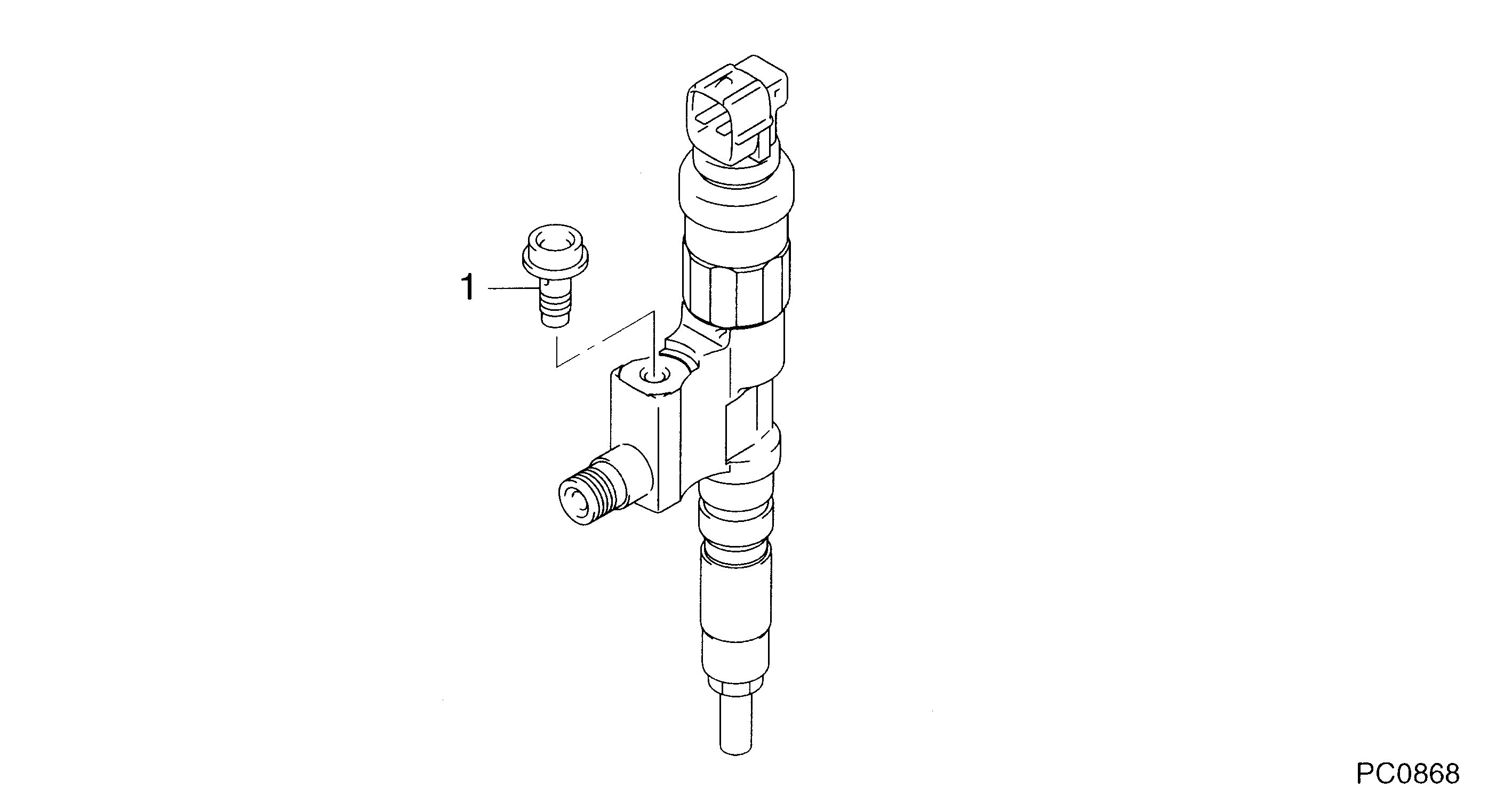
Information injector assy Denso
Product
Injector
Vehicle engine
COASTER N04C-T
Engine
N04C-T
Serial start-end
0905-
Info
Injector Nozzle
TOYOTA
INJECTOR ASSY
AA
- *1 P/N:23670-79095,-79096 (095000-8470 + GASKET)
- *2 P/N:23670-E9290,-E9291 (095000-8470 + GASKET)
Compare Prices: .
As an associate, we earn commssions on qualifying purchases through the links below

6 Bags Common Rail Injector Repair Kit For 095000-5050 095000-9510 095000-8480 095000-8470 095000-6550 095000-6541 095000-6520 - (Style: A, Color: For 095000-9510)
Generic Color: For 095000-9510
Generic Color: For 095000-9510

Injector 095000-8470 diesel common rail injector assembly Nozzle diesel engine reman - (Color: 095000-8470)
Generic Color: 095000-8470
Generic Color: 095000-8470
You can buy:

Components :
Scheme #.#:
№
Qty
Part num
Name
Remarks
Manufacture num
000
[01]
09500-08470
INJECTOR ASSY
23670-E0410
TOYOTA
Include in ##:
09500-08470
as INJECTOR ASSY
Nozzle Specification:
Parts number
0950008470 HINO
Nozzle
First opm
First op
Second om
Second op
-
Torquen
Torque
Prelift
Max lift
Engine
LIESSE N04C-T
Information
Cross reference number
Part num
Firm num
Firm
Name
09500-08470
23670-E041
TOYOTA
INJECTOR ASSY
0950008470
23670-E0410
HINO
INJECTOR ASSY
0950008470
23670-E0410
TOYOTA
INJECTOR ASSY
Information:
Keep all parts clean from contaminants. Contaminants put into the system may cause rapid wear and shortened component life.
1. Put compression on valve spring (2) with tool (A), and remove locks (1).2. Remove tool (A), rotocoil, spring, valve stem oil shield and valve. Put identification marks on valves with respect to their location in the cylinder head. 3. Check the spring force with tool (B). The spring force is 257 25 N (57.8 5.6 lb.). The length of spring under test force is 44.86 mm (1.766 in). The free length after test is 52.07 mm (2.050 in).4. Perform Steps 1 through 3 again for the remainder of the valves. The following steps are for the installation of the valves.5. Put clean engine oil on the valve stems. Install the valve, oil shield, spring (2) and rotocoil in the cylinder head. 6. Put tool (A) in position on the valve spring, and install the locks with tool (C).
Locks can be thrown from valve when the compressor is released if they are not in their correct position on valve stem. Personal injury can be the result if not carefully removed.
7. Remove tool (A), and hit the top of valve with a plastic hammer be sure the locks are in their correct position on valve.8. Do Steps 5 through 7 again for the remainder of the valves.End By:a. install spacer plate