Rating:
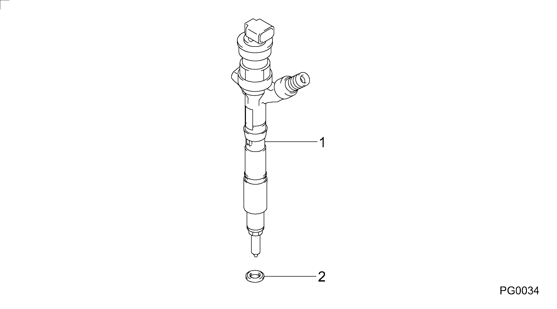
Information injector assy Denso
Product
Injector
Vehicle engine
LAND CRUISER 1KD-FTV
Engine
1KD-FTV
Serial start-end
0810-
Info
This is the supply parts for 095000-8140.
Injector Nozzle
Components :
Scheme #.#:
№
Qty
Part num
Name
Remarks
Manufacture num
000
[01]
09500-08230
INJECTOR ASSY
23670-39345
TOYOTA
Include in ##:
09500-08230
as INJECTOR ASSY
Nozzle Specification:
Parts number
0950008230 TOYOTA
Nozzle
First opm
First op
Second om
Second op
-
Torquen
Torque
Prelift
Max lift
Engine
LAND CRUISER 1KD-FTV
Information
095000-8230 consists of 095000-8140 and a gasket.
Cross reference number
Part num
Firm num
Firm
Name
09500-08230
23670-3934
INJECTOR ASSY
0950008230
23670-39345
TOYOTA
INJECTOR ASSY
Information:
The turbocharger does not have to be removed from the engine in order to remove the wastegate.1. Remove two clamps (1) and hose (2). 2. Remove retainer (4) and two nuts (3). 3. Remove three mounting bolts (6) and bracket (5).Disassemble Turbocharger (Schweitzer S4A)
Start By:a. remove turbocharger 1. Install the turbocharger on tool (A) as shown.2. Put alignment marks on three housings of the turbocharger for correct alignment during assembly. Loosen clamp (2), and remove the clamp and housing (1) from housing assembly (3). 3. Loosen clamp (4), and remove housing assembly (3) from housing (5). 4. Put the cartridge group in position in tool (B) as shown.
When the nut is loosened, do not put a side force on the shaft. This can result in a bent shaft.
5. Use a 5S9566 Sliding T-Wrench and a universal socket (6) to remove the nut that holds the compressor wheel to the wheel assembly.6. Remove compressor wheel (7) and the shims from wheel assembly (8).7. Remove housing assembly (3). 8. Remove ring (9) and backplate (10). 9. Use tool (C), and remove snap ring (11). 10. Remove insert (12) and sleeve (13). 11. Remove ring (14). 12. Remove two screws (15) and deflector (16). 13. Remove ring (18) and bearing assembly (17). 14. Remove sleeve (19) and ring (20). 15. Remove O-ring seal (23). Use tool (D), and remove snap ring (22).16. Remove bearing (21). Remove the snap ring behind the bearing with tool (D). 17. Use tool (D), and remove snap ring (25). Remove bearing (24). Remove the snap ring behind the bearing with tool (D).18. Check all the parts of the turbocharger for damage. If the parts are damaged, use new parts for replacement. See Special Instruction, Form No. SMHS6854, for Turbocharger Reconditioning. Also, see Guidelines For Reusable Parts, Form No. SEBF8018.Assemble Turbocharger (Schweitzer S4A)
1. Make sure that all of the oil passages in the turbocharger cartridge housing are clean and free of dirt and foreign material. Do not put oil on any parts of the turbocharger until after the compressor wheel has been installed. After the turbocharger has been assembled, pour clean engine oil into the oil inlet of the turbocharger.
Make sure that the snap rings that hold bearings (24) and (21) in position in housing assembly (3) are installed with the round edge of the outside diameter toward the bearing.
2. Install the snap ring behind bearing (24) with tool (D). Install bearing (24).3. Use tool (D), and install snap ring (25). 4. Install the snap ring behind bearing (21) with tool (D). Install bearing (21).5. Use tool (D), and install snap ring (22). 6. Put wheel assembly (8) in position on tool (B) as shown. Put backplate (10) in position on the wheel assembly. Put 6V2055 High Vacuum Grease in the groove for seal ring (9) at assembly to one half or more of the depth of the groove all the way around.7. Install ring (9) in the groove in wheel assembly (8). 8. Install housing