Rating:
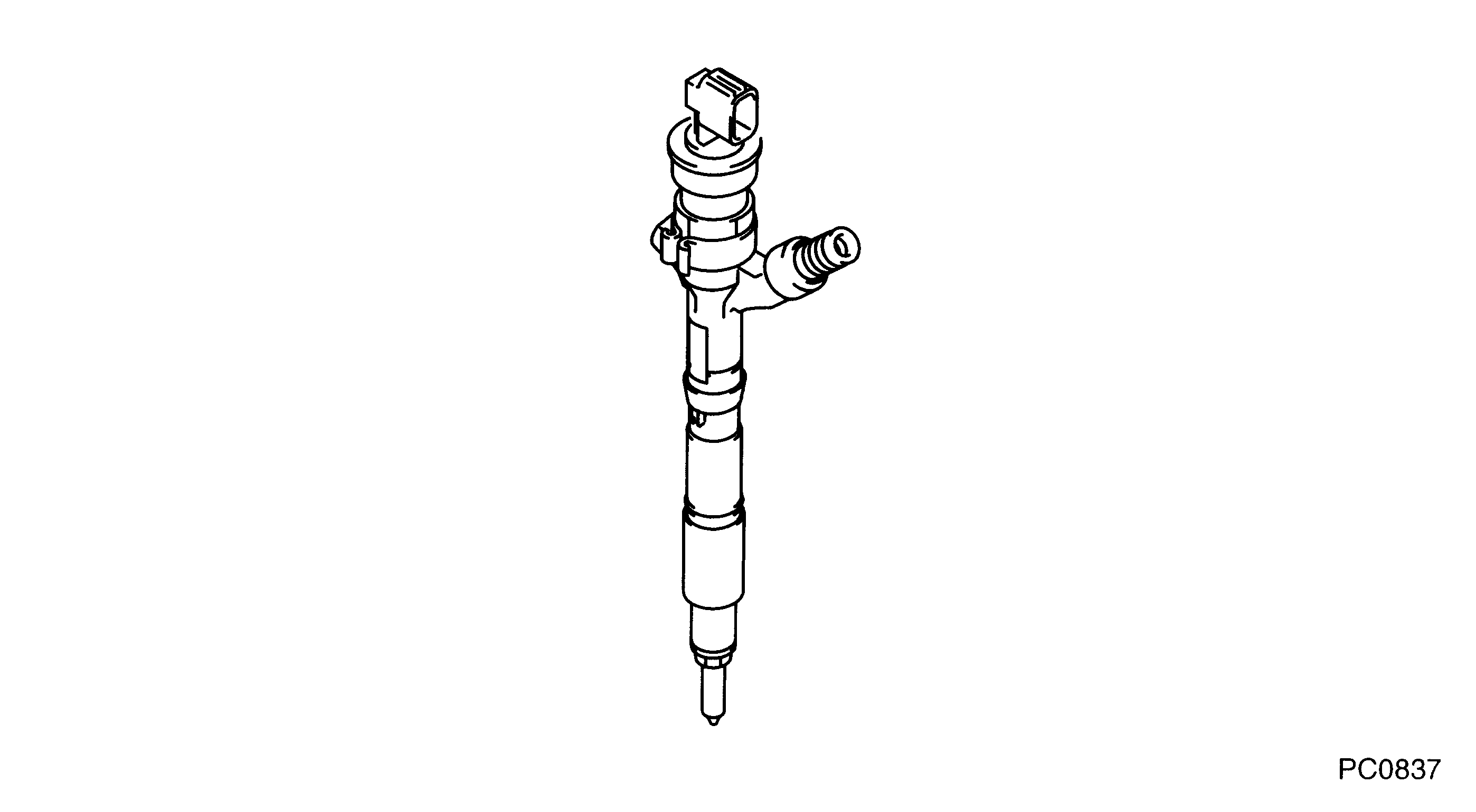
Information injector assy Denso
Product
Injector
Vehicle engine
AVENSIS 1CD-FTV
Engine
1CD-FTV
Serial start-end
0503-
Info
Exchange Unit P/N : 095000-6200(With gasket). This is not for Exchange Service.
Injector Nozzle
TOYOTA
INJECTOR ASSY
AA
- 095000-615# CANNOT BE SUPPLIED. SPARE PART NUMBER IS
- 095000-620#(-615# AND A GASKET).
Compare Prices: .
As an associate, we earn commssions on qualifying purchases through the links below

$49.99
25 Oct 2024
KR: Adabus
Diesel Control Valve Plate 07# Engine Assembly 07 For DENS0 Injector 095000-6150 095000-6151 23670-30300 23670-30080 - (Color: 10)
Generic Color: 10 || Other part number: 07#/04#/517#/507#/31#/509#/10#/19#/34#/504# || Interchange part number: 07#/04#/517#/507#/31#/509#/10#/19#/34#/504# || Material type: STEEL || Item height: Standard size
Generic Color: 10 || Other part number: 07#/04#/517#/507#/31#/509#/10#/19#/34#/504# || Interchange part number: 07#/04#/517#/507#/31#/509#/10#/19#/34#/504# || Material type: STEEL || Item height: Standard size
Components :
Scheme #.#:
№
Qty
Part num
Name
Remarks
Manufacture num
000
[01]
09500-06150
INJECTOR ASSY
NO SUPPLY
23670-27051
TOYOTA
Include in ##:
Nozzle Specification:
Parts number
0950006150 TOYOTA
Nozzle
First opm
First op
Second om
Second op
-
Torquen
Torque
Prelift
Max lift
Engine
AVENSIS 1CD-FTV
Information
095000-615# is not for Exchange Service. Exchanage Unit P/N:095000-620#(With gasket).
Cross reference number
Part num
Firm num
Firm
Name
09500-06150
23670-2705
TOYOTA
INJECTOR ASSY
0950006150
23670-27051
TOYOTA
INJECTOR ASSY
Information:
1. Remove the air inlet pipe at the turbocharger.2. Remove the exhaust pipe and exhaust coupling from the turbocharger. 3. Remove the two bolts that fasten turbocharger oil supply line (2) to turbocharger. Remove clip (3).4. Loosen fitting (4). Remove the two bolts that fasten turbocharger oil return line (2) to the turbocharger.5. Remove bolts, nuts and washers that fasten turbocharger (1) to the exhaust manifold. 6. Remove the three bolts that hold heat shield (6). Install in reverse order.Disassemble Turbocharger (AiResearch TV61)
Start By:a. remove turbocharger
Keep all parts clean from contaminants. Contaminants put into the system may cause rapid wear and shortened component life.
1. Install the turbocharger on tool (A) as shown. Put marks on the three housings of the turbocharger for correct installation and alignment at assembly.2. Loosen clamp (1) and remove compressor housing (2) and the clamp from the cartridge assembly. 3. Loosen clamp (3) and remove cartridge assembly (4) from turbine housing (5).
To prevent a bent shaft, do not put a side force on the turbine shaft when the compressor wheel nut is loosened.
4. Install tool (C) in tool (B) and put the cartridge assembly in tool (C) as shown. Use tool (D) to remove the not that holds compressor wheel (6). 5. Use a press to push the turbine shaft out of compressor wheel (6) and the cartridge housing. Remove compressor wheel (6). 6. Put the turbine shaft in tool (C). Remove seal ring (8) and shroud (7).7. Use tool (E) to make sure the turbocharger shaft is straight. See Special Instruction, Form No. SMHS6998. 8. Bend the tabs of the locks from bolts (10). Remove the bolts and locks.9. Remove backplate assembly (11) and spacer (9). 10. Remove seal rings (12). 11. Remove thrust collar (13). 12. Remove seal ring (14) and thrust bearing (15). If the bearings are to be used again, put identification on them as to their location for correct assembly. 13. Remove bearing (16) and the washer below the bearing. 14. Use tool (F) to remove snap rings (17) and (18).15. Remove bearing (19) and washer (20).16. Use tool (F) to remove snap ring (21) if necessary.17. Check all the parts of the turbocharger for damage. If the parts have damage, use new parts for replacement. See Special Instruction, Form No. SMHS6854, for Turbocharger Reconditioning. Also, see Guideline For Reusable Parts, Form No. SEBF8018.Assemble Turbocharger (AiResearch TV61)
1. Make sure all of the oil passages in the turbocharger cartridge housing backplate assembly and bearings are clean and free of dirt and foreign material. Put clean engine oil on all parts of the cartridge at assembly. Make sure the round edge of the snap rings are toward the bearings when the snap rings are installed. 2. If necessary, use tool (A) to install snap ring (1) in the turbine end of the cartridge housing. 3. Install washer (2) and bearing (3). Use tool (A) to install snap ring (4).4. Use tool (A) to install snap ring (5). 5. Install the washer