Rating:
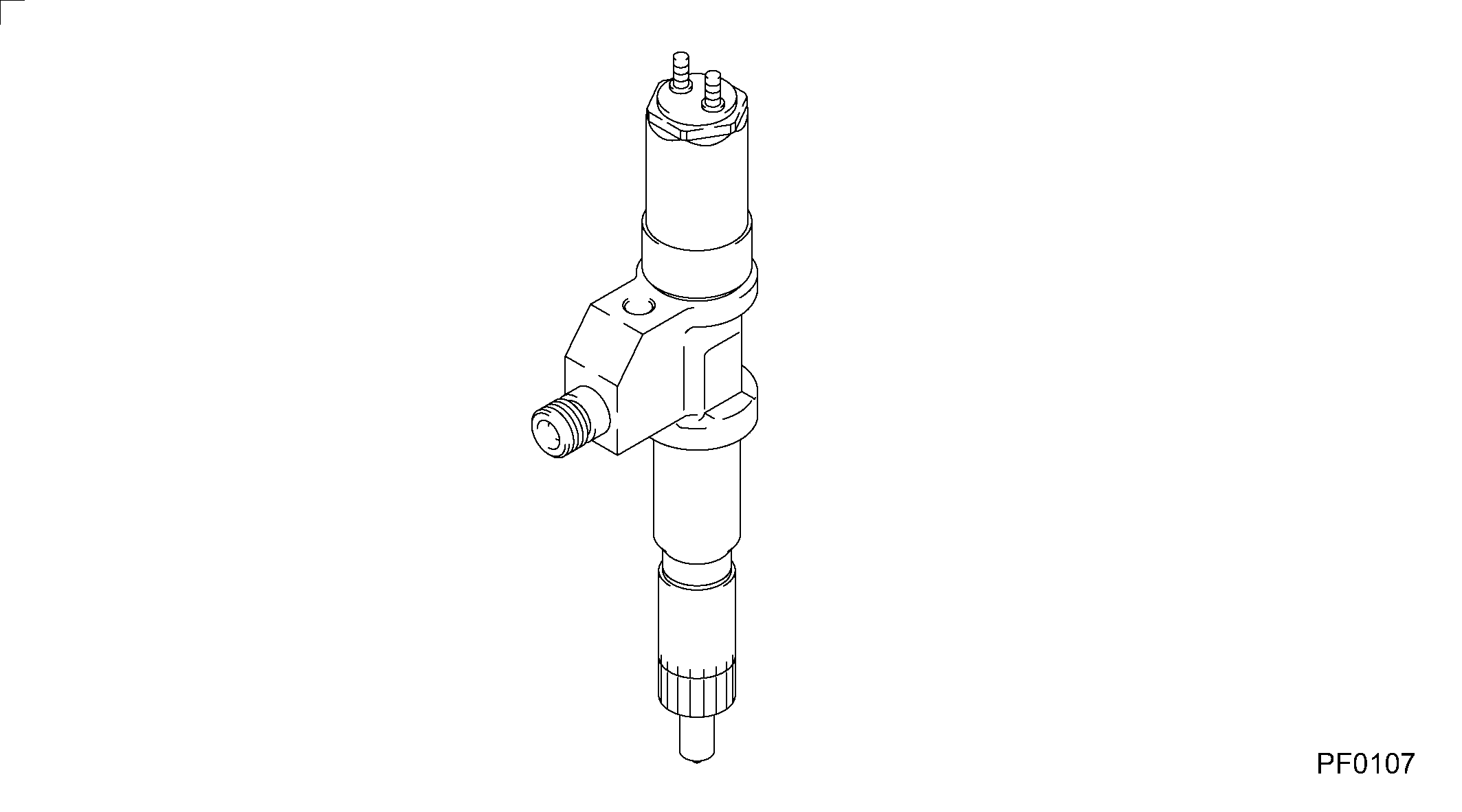
Information injector assy Denso
Product
Injector
Vehicle engine
N SERIES 6WG1
Engine
6WG1
Serial start-end
0601-
Info
Injector Nozzle
Compare Prices: .
As an associate, we earn commssions on qualifying purchases through the links below

Fuel Injector 095000-5510 095000-5511 095000-5516 095000-5517 8-97603415-0 8-97603415-7 8-97603415-8,Compatible For SU-ZU GIGA
QEDADXD OEM NO. : 095000-5510, 095000-5511, 095000-5516, 095000-5517, 8-97603415-0, 8-97603415-7, 8-97603415-8 || Our fuel injectors deliver precise fuel injection to optimize engine performance and fuel efficiency. || Manufactured with OEM-compatible design, they ensure a perfect fit for seamless installation across various vehicle models. || Built with durable materials, they withstand extreme conditions for long-lasting use. || Each injector is rigorously tested for flow rate, spray pattern, and leakage to guarantee reliable performance.
QEDADXD OEM NO. : 095000-5510, 095000-5511, 095000-5516, 095000-5517, 8-97603415-0, 8-97603415-7, 8-97603415-8 || Our fuel injectors deliver precise fuel injection to optimize engine performance and fuel efficiency. || Manufactured with OEM-compatible design, they ensure a perfect fit for seamless installation across various vehicle models. || Built with durable materials, they withstand extreme conditions for long-lasting use. || Each injector is rigorously tested for flow rate, spray pattern, and leakage to guarantee reliable performance.

YIQONAPEL 095000-5511/095000-6070/095000-6471/095000-6591/095000-6700 Electric Injector Valve Rod(095000-5511)
YIQONAPEL Wide compatibility: Compatible with a variety of vehicle models and engines. || Fuel atomization enables more complete combustion, providing powerful output. || Low - noise operation: Optimize the internal structure to reduce fuel injection noise. || Utilize technology to respond to engine commands and accurately complete fuel injection. || Stable and dependable: Maintains stable functioning under various operating conditions, ensuring more stable driving.
YIQONAPEL Wide compatibility: Compatible with a variety of vehicle models and engines. || Fuel atomization enables more complete combustion, providing powerful output. || Low - noise operation: Optimize the internal structure to reduce fuel injection noise. || Utilize technology to respond to engine commands and accurately complete fuel injection. || Stable and dependable: Maintains stable functioning under various operating conditions, ensuring more stable driving.

Diesel Engine Parts Fuel Injector 095000-5511 095000-8871 095000-5215 095000-6353 095000-6593 Electric Syringe GZQJA16S29(095000-5511)
QEDADXD [Wide Compatibility]:Our Diesel Engine Parts Fuel Injectors, including 095000-5511, 095000-8871, 095000-5215, 095000-6353, and 095000-6593 with Electric Syringe GZQJA16S29, are compatible with a range of diesel engines. Ensure seamless fit. || [Solve Engine Performance Issues]:If your engine has been suffering from rough idling, poor acceleration, or engine misfires, our fuel injectors can be the solution. Restore smooth operation and reliable performance. || [Durable Construction]:Constructed from high - grade materials, they can withstand the high - pressure environment within diesel engines. Enjoy long - term reliability and reduced maintenance requirements. || [Direct Installation]:Designed as direct replacement parts, installation is a breeze. Even DIY enthusiasts can quickly swap them in, saving on costly mechanic fees. || [Quality - Tested]:Each injector, undergoes strict quality control tests. Trust in their reliability for your diesel engine.
QEDADXD [Wide Compatibility]:Our Diesel Engine Parts Fuel Injectors, including 095000-5511, 095000-8871, 095000-5215, 095000-6353, and 095000-6593 with Electric Syringe GZQJA16S29, are compatible with a range of diesel engines. Ensure seamless fit. || [Solve Engine Performance Issues]:If your engine has been suffering from rough idling, poor acceleration, or engine misfires, our fuel injectors can be the solution. Restore smooth operation and reliable performance. || [Durable Construction]:Constructed from high - grade materials, they can withstand the high - pressure environment within diesel engines. Enjoy long - term reliability and reduced maintenance requirements. || [Direct Installation]:Designed as direct replacement parts, installation is a breeze. Even DIY enthusiasts can quickly swap them in, saving on costly mechanic fees. || [Quality - Tested]:Each injector, undergoes strict quality control tests. Trust in their reliability for your diesel engine.
Components :
Scheme #.#:
№
Qty
Part num
Name
Remarks
Manufacture num
000
[01]
09500-05511
INJECTOR ASSY
-0505
8-97603415-1
ISUZU
000
[01]
09500-05511
INJECTOR ASSY
0505-
8-97603415-2
ISUZU
Include in ##:
09500-05511
as INJECTOR ASSY
09500-05511 INJECTOR ASSY
Cross reference number
Part num
Firm num
Firm
Name
09500-05511
8-97603415
INJECTOR ASSY
Information:
Start By:
Do not let the tops of the nozzles turn while the fuel lines are loosened. The nozzles will be damaged if the top of the nozzle turns in the body. Defective fuel nozzles will damage the engine due to improper spray patterns.
a. remove fuel injection lines
Keep all parts clean from contaminants. Contaminants put into the system may cause rapid wear and shortened component life.
1. Remove clamp (1). 2. Install tool (A). Move the screw out of the poller enough to engage the inside lip of the puller on the lower stepped diameter of the nozzle.
Do not exceed a torque of 17 N m (13 lb ft) on the screw in tooling (A) to remove the nozzle. Added force can cause the stem of the nozzle to vend or break off.
3. With the nozzle bleed screw seen through the clearance hole in tooling (A), turn the screw down until the tip of the button goes down into the thread in the hole for the nozzle clamp bolt. When tooling (B) is used, the nozzle must be replaced.4. If the nozzle can not be removed with tooling (A), tooling (B) must be used.
Hold tool (B) so the center line of tool (B) is the same as the extended center line of fuel injection nozzle (2). This will prevent distortion of the fuel injection nozzle which can cause the nozzle to bend or break off.
5. Remove the protective cap and install tooling (B).6. Use the slide hammer to remove fuel injection nozzle (2).7. For nozzles removed using tool (A), remove the carbon dam seal on the end of the nozzle. The following steps are for the installation of the fuel injection nozzles. Tool (C) must be modified by drilling it out to a diameter of 8.5 mm (.344 in) and to a depth of 1.5 mm (.060 in) before it can be used on the 8N7002 Fuel Nozzles. 8. Use tool (C) to install carbon dam seal (4).9. To clean the nozzles, see Special Instruction SEHS7292 for the use of tooling (D).10. Install new seal (5). 11. Use tool (D) to clean the bore for the fuel injection nozzle. Use as open end wrench of tap driver to turn tool (E).
Do not let the tops of the fuel nozzles turn when the fuel lines are tightened. The nozzles will be damaged if the top of the nozzle turns in the body.
12. Install fuel injection nozzle (3). Put the nozzle in position with the bleed screw away from the rocker arm cover and install clamp (1).End By:a. install fuel injection lines
Perform Scheduled Oil Sampling after performing service work to check for fuel leakage and contaminants left in the system following repair. Contaminants put into the system may cause rapid wear and shortened component life.