Rating:
Information injector assy Denso
Compare Prices: .
As an associate, we earn commssions on qualifying purchases through the links below

Fuel Injector 095000-5274 23670-E0250 095000-6593 095000-5405 095000-6364 095000-6363 095000-6353 23670-E0050
QEDADXD [OEM NO.]: 095000-5274, 23670-E0250, 095000-6593, 095000-5405, 095000-6364, 095000-6363, 095000-6353, 23670-E0050 || [Perfect Compatibility]:These nozzles are precisely engineered to fit common rail fuel injectors, ensuring seamless integration. || [Improved Fuel Efficiency]:Precise fuel injection control helps boost engine efficiency, reducing fuel consumption and saving you money. || [Optimal Combustion Results]:The nozzles promote better fuel atomization, leading to more complete combustion and improved overall engine performance. || [User - Friendly Installation]:With a user - friendly design, installing these nozzles is quick and hassle - free, saving you valuable time and effort.
QEDADXD [OEM NO.]: 095000-5274, 23670-E0250, 095000-6593, 095000-5405, 095000-6364, 095000-6363, 095000-6353, 23670-E0050 || [Perfect Compatibility]:These nozzles are precisely engineered to fit common rail fuel injectors, ensuring seamless integration. || [Improved Fuel Efficiency]:Precise fuel injection control helps boost engine efficiency, reducing fuel consumption and saving you money. || [Optimal Combustion Results]:The nozzles promote better fuel atomization, leading to more complete combustion and improved overall engine performance. || [User - Friendly Installation]:With a user - friendly design, installing these nozzles is quick and hassle - free, saving you valuable time and effort.

$216.74
20 Mar 2025
CN: ziwangcjx
IMIFAFTAbT New Fuel Injector 095000-5274 23670-E0250 Compatible with Hino J08E Engine
IMIFAFTAbT Product name: Fuel Injector || Warranty:1year || Compatible with Hino J08E Engine || Part Number:095000-5274 23670-E0250 || Important Note:1.Please double check that this product fits your car before purchasing check your part number,photo. 2.Since the effect of light is different between the display and the display, the actual color may be different from the color of the image.
IMIFAFTAbT Product name: Fuel Injector || Warranty:1year || Compatible with Hino J08E Engine || Part Number:095000-5274 23670-E0250 || Important Note:1.Please double check that this product fits your car before purchasing check your part number,photo. 2.Since the effect of light is different between the display and the display, the actual color may be different from the color of the image.

$247.79
17 Feb 2025
CN: QYWD
1X Fuel Injector Model 095000-5270 095000-5274 for Hino 500 J08E Engine
TUWODE Part Number: 095000-5270 095000-5274 || Item Type: Fuel Injector || Applicable Models: Fit for Hino 500 J08E Engine || Well-functioning fuel injectors ensure the correct air-fuel ratio, which is essential for minimizing harmful emissions. || Fuel is broken into fine droplets for optimal air mixing and enhanced combustion efficiency.
TUWODE Part Number: 095000-5270 095000-5274 || Item Type: Fuel Injector || Applicable Models: Fit for Hino 500 J08E Engine || Well-functioning fuel injectors ensure the correct air-fuel ratio, which is essential for minimizing harmful emissions. || Fuel is broken into fine droplets for optimal air mixing and enhanced combustion efficiency.
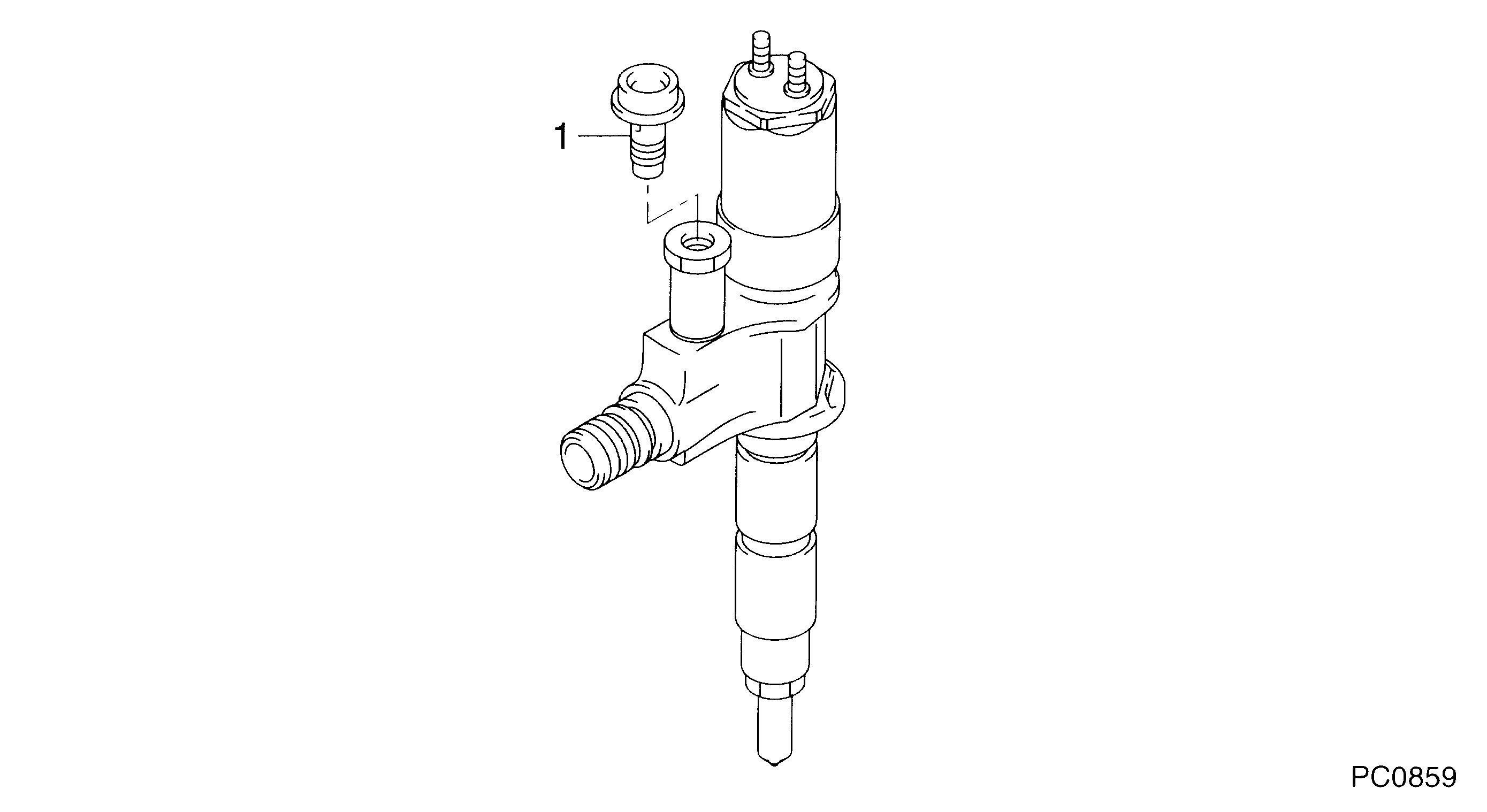
Components :
Scheme #.#:
№
Qty
Part num
Name
Remarks
Manufacture num
000
[01]
09500-05274
INJECTOR ASSY
0807-
23670-E0251
HINO
Include in ##:
09500-05274
as INJECTOR ASSY
Cross reference number
Part num
Firm num
Firm
Name
09500-05274
23670-E025
INJECTOR ASSY
Information:
Remove Jacobs Engine Brake
1. Loosen clamp (1), and disconnect breather tube (2) from the hose.2. Remove four bolts (5) that hold the elbow to the inlet manifold. Remove elbow (3) and air pipe (4) as a unit. 3. Remove bolts (7) that hold the valve covers in place. Remove valve covers (6). 4. Disconnect solenoid lead wires (8) and (10) from the terminal in the Jacobs spacer.5. Remove eight Jacobs nuts (9) and four Jacobs bolts that hold the Jacobs spacers to the valve cover bases. Remove Jacobs spacers (11). Do Steps 6 through 13 for each end of the engine. The front half of the engine is shown.6. Remove four Jacobs studs (12) and Jacobs washers. Remove three bolts (13), and remove valve cover base (14). 7. Remove Jacobs nuts (15), Jacobs washers, Jacobs bolts (16) and the Jacobs washers that hold the Jacobs brake housing assembly in place.8. Remove Jacobs brake housing assembly (17). The Jacobs brake for the 3406B Truck Engine has only one support bracket (18).9. Remove Jacobs head bolts (19), and remove Jacobs support brackets (18) from the cylinder head. 10. Remove inner fuel lines (20). 11. Remove Jacobs washers (21) and Jacobs shims (22) from the Jacobs stud assemblies. 12. Remove bolt (24) and two Jacobs stud assemblies (23) that hold the rocker shaft assembly to the head. Remove rocker shaft assembly (25). 13. Remove Jacobs exhaust valve bridges (27) from the exhaust valves only. The intake valves have the Caterpillar intake valve bridges. Remove the Caterpillar intake valve bridges (26). 14. Remove Jacobs engine control switch (29) from the governor housing. Remove Jacobs actuator arm (28).Install Jacobs Engine Brake
Do each step for each end of the engine. The front half is shown.1. Put clean engine oil on the bridges and dowels.2. Install Jacobs exhaust valve bridges (1) and the Caterpillar intake valve bridges (2) on the dowels.3. Keep hand pressure on the bridges, and turn the adjustment screw clockwise until contact is made with the valve stem. Turn the screw an extra 20° to 30°. This will make the dowel straight in the guide and compensate for gap (slack) in the threads. Hold the adjustment screw in this position, and tighten the locknut to a torque of 28 4 N m (21 3 lb.ft.). 4. Put rocker shaft assembly (3) in position on the cylinder head. 5. Install Jacobs washers (4) on the Jacobs stud assemblies (6). Put clean oil on the threads, and install washer and bolt (5) and Jacobs stud assemblies (6). Tighten the center bolt and Jacobs stud assemblies in increments of 70 N m (50 lb.ft.) each until a final torque of 450 N m (330 lb.ft.) is obtained.6. Make an adjustment to the valves to have a clearance of .015 (0.38 mm) for the intake valves and .030 (0.76 mm) for the exhaust valves. Tighten the locknuts to a torque of 28 4 N m (21 3 lb.ft.), and check the