Rating:
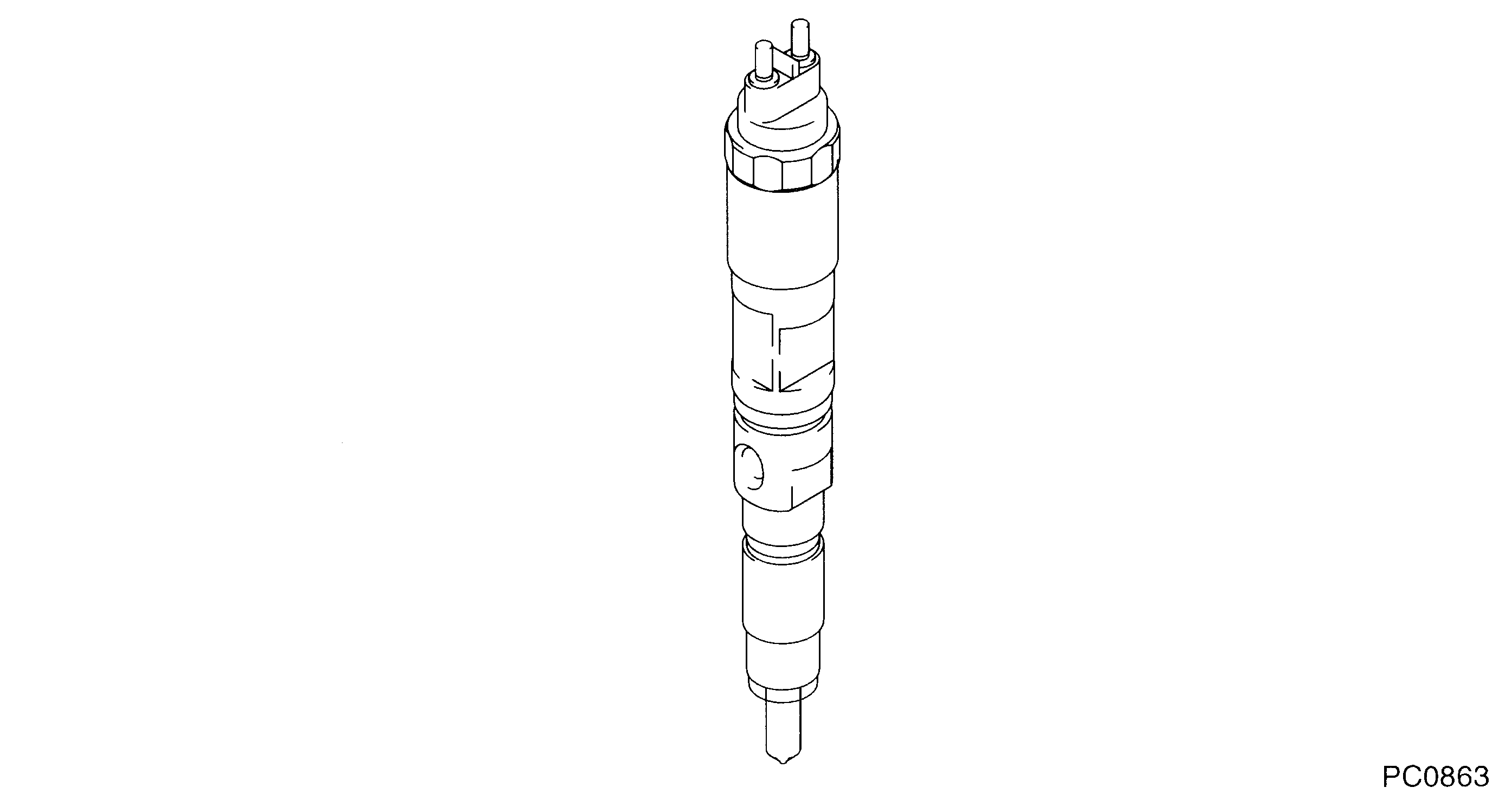
Information injector assy Denso
Product
Injector
Vehicle engine
agricultural machine 6081
Engine
6081
Serial start-end
0208-
Info
G2 Type
Injector Nozzle
Compare Prices: .
As an associate, we earn commssions on qualifying purchases through the links below

095000-5050 095000-5051 RE507860 RE516540 RE519730 CR Fuel Injector for John Deere 4.5L 6.8L 4045T 6068T Tier 3 4 cyl Engine 4720 6320 6420 6520 6620 6820 643J 843J 670 9550 Loader Grader
HIRINTOL 🔸Replace Part Number: 095000-5050, 095000-5051, RE507860, RE516540, RE519730, AP52800, AP52900. || 🔸Engine Model: For John Dere 4.5L 6.8L 4045T 6068T Tier 3 4 cyl S350 Engine. || 🔸Compatible Model: For John Dere Models: 4720, 624J, 6320 6420 6420S 6520 6620 6820 6920 6920S 7720 7820 7920, 643J 843J 843K, 670C 670CH 672CH, 670D & 672, 9540I WTS 9560I WTS 9580I WTS, 9550 9550SH, 4045HF 6068HF. || 🔸High-Standard Production: Precision-controlled fuel injectors, OE specification production, high quality raw materials, high standard production, excellent performance, perfect fit. || 🔸Durable Material: Manufactured with premium, long-lasting materials to meet original factory standards and undergo strict quality control, strong and durable, long service life.
HIRINTOL 🔸Replace Part Number: 095000-5050, 095000-5051, RE507860, RE516540, RE519730, AP52800, AP52900. || 🔸Engine Model: For John Dere 4.5L 6.8L 4045T 6068T Tier 3 4 cyl S350 Engine. || 🔸Compatible Model: For John Dere Models: 4720, 624J, 6320 6420 6420S 6520 6620 6820 6920 6920S 7720 7820 7920, 643J 843J 843K, 670C 670CH 672CH, 670D & 672, 9540I WTS 9560I WTS 9580I WTS, 9550 9550SH, 4045HF 6068HF. || 🔸High-Standard Production: Precision-controlled fuel injectors, OE specification production, high quality raw materials, high standard production, excellent performance, perfect fit. || 🔸Durable Material: Manufactured with premium, long-lasting materials to meet original factory standards and undergo strict quality control, strong and durable, long service life.

TSIOHKBS Nozzle Part DLLA133P814 095000-5050,
TSIOHKBS
TSIOHKBS

Components :
Scheme #.#:
№
Qty
Part num
Name
Remarks
Manufacture num
000
[01]
09500-05050
INJECTOR ASSY
Include in ##:
09500-05050
as INJECTOR ASSY
Nozzle Specification:
Parts number
0950005050 JOHN DEERE
Nozzle
First opm
First op
Second om
-
Second op
-
Torquen
-
Torque
-
Prelift
-
Max lift
-
Engine
agricultural machine 6068
Information
G2 Type
Include as Nozzle:
Cross reference number
Part num
Firm num
Firm
Name
09500-05050
INJECTOR ASSY
Information:
1. Loosen two bolts (2) and two nuts (3). Remove bolt (1), and remove fan drive belts (4). 2. Remove the nuts and bolts that hold the fan drive in place. Remove fan drive (5).Install Fan Drive
1. Put fan drive (1) in position on the timing gear cover. 2. Install bolts (3) and the nuts loosely. Make a replacement of the belts as a set only.3. Install fan belts (4). Install bolt (2). Make an adjustment to the belt tension with tool (A). Measure the belt farthest away from the engine. Tighten new belts to a gauge indication of 120 5. After the engine is operated at high idle for a minimum of 30 minutes, make another adjustment to the belt tension. The correct tension for used belts is a gauge indication of 90 10.3. Tighten bolts (3) and the nuts that hold the fan drive in place.Disassemble Fan Drive
START BY:a. remove fan drive This is a typical later model fan drive. 1. Remove two bolts (2) that hold the fan adapter to the pulley.2. Remove fan adapter (1) from the pulley. 3. Remove bolts (3) and washer (4). Remove seal (5). 4. Remove pulley (8) from bracket (6).5. Remove bearing (10) and spacer (9) from the pulley. Remove spacer (7), seal (11) and bearing (12) from the pulley.Assemble Fan Drive
1. Install bearing (2) in the rear of pulley (3). 2. Install lip-type seal (1) with tooling (A). The lip of the seal must be away from the bearing. Put 5P960 Multipurpose Type Grease on the lip of the seal.3. Install spacer (5) so the end with the taper is toward the inside of pulley (3).4. Install spacer (6) and bearing (4) in the front of the pulley. 5. Put seal (7) on the front of the pulley. Install the pulley on bracket (8). 6. Install washer (10) and bolts (9) that hold the pulley in position.7. Install the fan drive adapter on the pulley.8. Fill the fan drive with 5P960 Multipurpose Type Grease.