Rating:
Information injector assy Denso
Compare Prices: .
As an associate, we earn commssions on qualifying purchases through the links below

$755.00
09 Mar 2025
CN: ziwangcjx
IMIFAFTAbT 095000-5003 095000-5004 095000-5005 095000-5006 Fuel Injector 4PCS For for Isuzu 4HJ1 4HK1 4HK1-TCC 4HK1-TCS 5.2L Engine NPR NQR NRR N-Series Trucks
IMIFAFTAbT Part Name:Fuel Injector 095000-5003 095000-5004 095000-5005 095000-5006 || Part Number:095000-5003 095000-5004 095000-5005 095000-5006 || APPlication: Compatible with for Isuzu 4HJ1 4HK1 4HK1-TCC 4HK1-TCS 5.2L Engine NPR NQR NRR N-Series Trucks || If you are not sure if the product is suitable please leave us a message and send us your original || product picture and part number and we will send the correct part after confirmation
IMIFAFTAbT Part Name:Fuel Injector 095000-5003 095000-5004 095000-5005 095000-5006 || Part Number:095000-5003 095000-5004 095000-5005 095000-5006 || APPlication: Compatible with for Isuzu 4HJ1 4HK1 4HK1-TCC 4HK1-TCS 5.2L Engine NPR NQR NRR N-Series Trucks || If you are not sure if the product is suitable please leave us a message and send us your original || product picture and part number and we will send the correct part after confirmation

$172.00
09 Mar 2025
CN: ziwangcjx
IMIFAFTAbT 095000-5003 095000-5004 095000-5005 095000-5006 Fuel Injector For for Isuzu 4HJ1 4HK1 4HK1-TCC 4HK1-TCS 5.2L Engine NPR NQR NRR N-Series Trucks
IMIFAFTAbT Part Name:Fuel Injector 095000-5003 095000-5004 095000-5005 095000-5006 || Part Number:095000-5003 095000-5004 095000-5005 095000-5006 || APPlication: Compatible with for Isuzu 4HJ1 4HK1 4HK1-TCC 4HK1-TCS 5.2L Engine NPR NQR NRR N-Series Trucks || If you are not sure if the product is suitable please leave us a message and send us your original || product picture and part number and we will send the correct part after confirmation
IMIFAFTAbT Part Name:Fuel Injector 095000-5003 095000-5004 095000-5005 095000-5006 || Part Number:095000-5003 095000-5004 095000-5005 095000-5006 || APPlication: Compatible with for Isuzu 4HJ1 4HK1 4HK1-TCC 4HK1-TCS 5.2L Engine NPR NQR NRR N-Series Trucks || If you are not sure if the product is suitable please leave us a message and send us your original || product picture and part number and we will send the correct part after confirmation

$1,009.79
12 Feb 2025
CN: QYWD
0950005005 095000-5005 6X Fuel Injector for Denso Isuzu 4HJ1 6HJ1 Engine
TUWODE Part Number: 950005005 095000-5005 || Item Type: Fuel Injector || Applicable Models: Fit for Denso Isuzu 4HJ1 6HJ1 Engine || Well-functioning fuel injectors ensure the correct air-fuel ratio, which is essential for minimizing harmful emissions. || Fuel is broken into fine droplets for optimal air mixing and enhanced combustion efficiency.
TUWODE Part Number: 950005005 095000-5005 || Item Type: Fuel Injector || Applicable Models: Fit for Denso Isuzu 4HJ1 6HJ1 Engine || Well-functioning fuel injectors ensure the correct air-fuel ratio, which is essential for minimizing harmful emissions. || Fuel is broken into fine droplets for optimal air mixing and enhanced combustion efficiency.
Include in ##:
Cross reference number
Part num
Firm num
Firm
Name
09500-05005
8-97306071
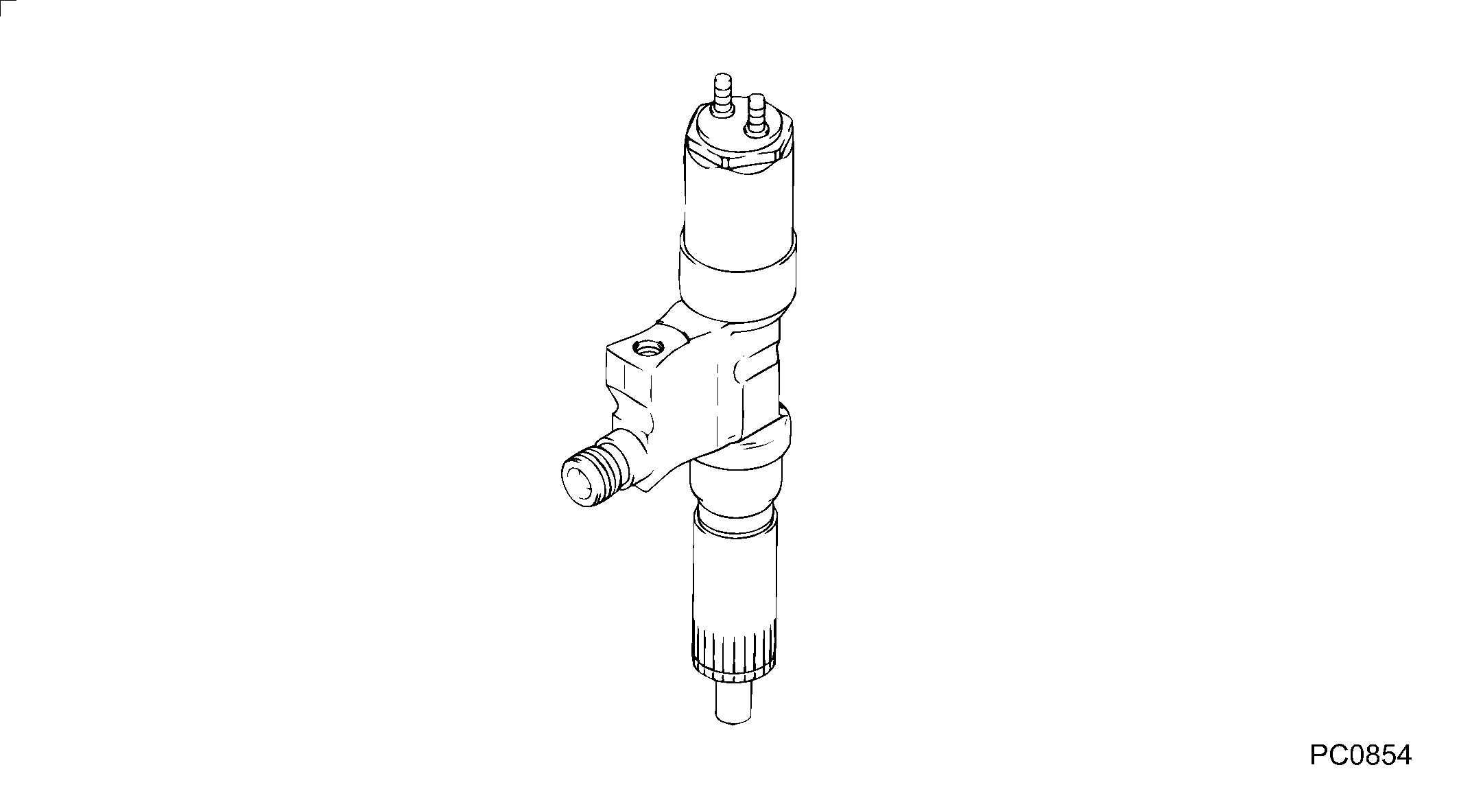
INJECTOR ASSY
Information:
1. Remove bolts (1) from the alternator bracket.2. Remove the bolts that hold plate (3), and remove the plate.3. Disconnect water line (2) from the air compressor. Turn the water line tee toward the lifting bracket in order to provide clearance to remove the head bolt. 4. Remove bolts (4) and (5) that hold the cylinder head assembly to the cylinder block.5. Fasten a hoist, and remove the cylinder head assembly. The weight is approximately 135 kg (300 lb.).
Do not put the cylinder head assembly down on a flat surface. This can cause damage to the fuel injection valves.
6. Remove the gasket and seals from the spacer plate.Install Cylinder Head Assembly
Be sure a new gasket has been installed between the spacer plate and the cylinder block. See Remove And Install Spacer Plate. 1. Thoroughly clean the spacer plate and the bottom surface of the cylinder head assembly. Install a new head gasket, new seals (1) and two O-ring seals (2). 2. Fasten a hoist, and put cylinder head assembly (3) in position on the cylinder block.3. Put 5P3931 Anti-Seize Compound on the threads of the cylinder head bolts. Install the cylinder head bolts and washers. Tighten the bolts in sequence shown in illustration A87019X1 on page 6-119.a. Tighten bolts 1 through 20 in number sequence to a torque of 270 25 N m (200 18 lb.ft.).b. Tighten bolts 1 through 20 in number sequence to a torque of 450 20 N m (330 15 lb.ft.).c. Tighten bolts 1 through 20 in number sequence to a torque of 450 20 N m (330 15 lb.ft.) by hand.d. Install the rocker shaft assemblies and push rods. See Install Rocker Shaft Assemblies And Push Rods.e. Tighten bolts 21 through 26 in number sequence to a torque of 270 25 N m (200 18 lb.ft.).f. Tighten bolts 21 through 26 in number sequence to a torque of 450 20 N m (330 15 lb.ft.).g. Tighten bolts 21 through 26 in number sequence to a torque of 450 20 N m (330 15 lb.ft.) by hand.h. Tighten the 3/8" bolts to a torque of 43 7 N m (32 5 lb.ft.). If the studs for the exhaust manifold were removed, install new studs, and tighten them to a torque of 25 4 N m (18 3 lb.ft.).4. Make an adjustment to the valves to have a clearance of 0.38 mm (.015 in.) for intake and 0.76 mm (.030 in.) for exhaust. Tighten the locknuts for the valve adjustment screws to a torque of 28 4 N m (21 3 lb.ft.).5. Install the valve cover bases and the inner fuel lines. See Install Rocker Shaft Assemblies And Push Rods.6. Install the valve covers. See Install Valve Covers. 7. Install plate (4).8. Connect the water line to the air compressor.9. Install bolts (5) for the alternator bracket.END BY:a. install exhaust manifoldb. install fuel injection linesc. install aftercooler