Rating:
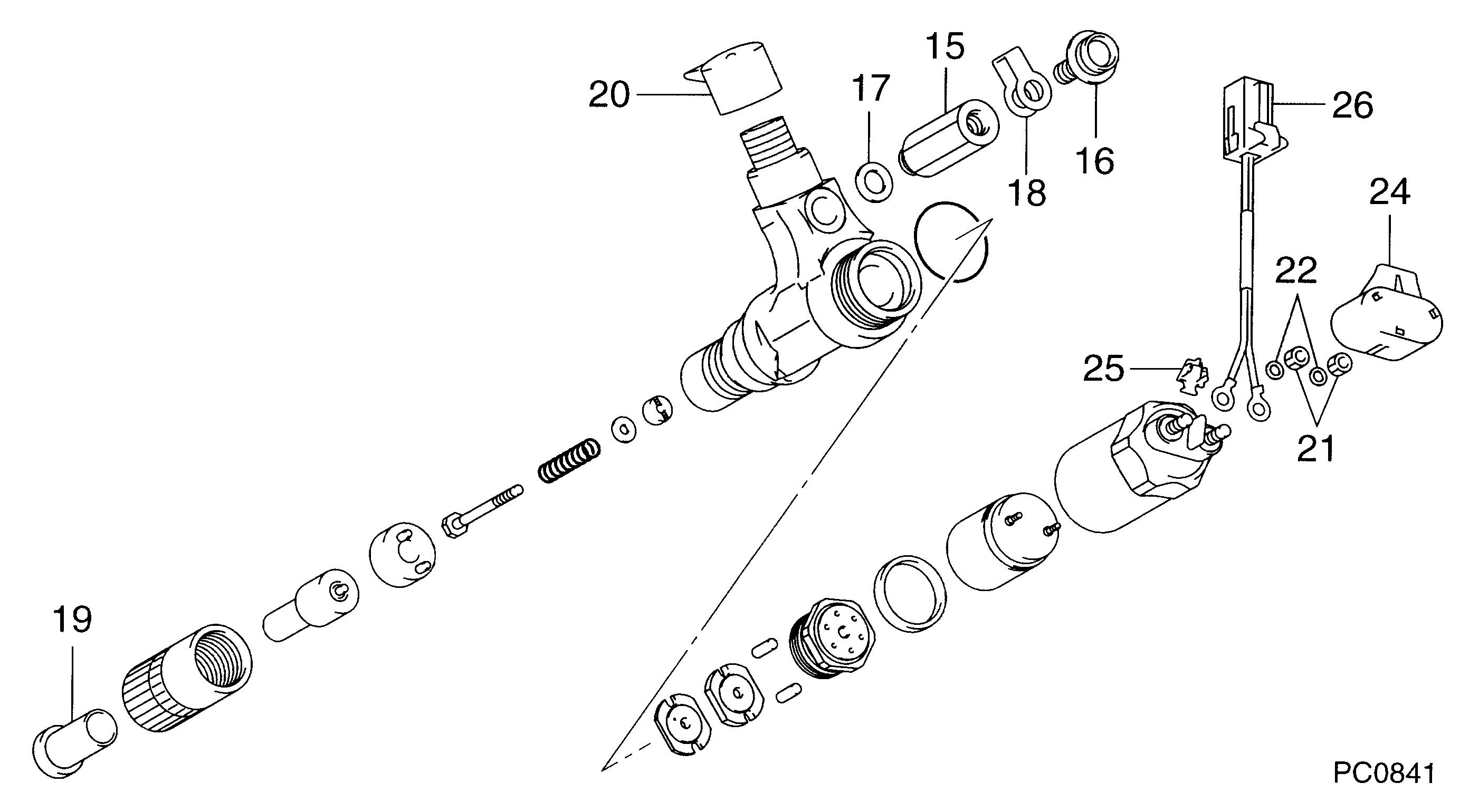
Information injector assy Denso
Product
Injector
Vehicle engine
DUTRO S05C
Engine
S05C
Serial start-end
0110-
Info
Injector Nozzle
Product
Injector
Vehicle engine
DYNA S05C
Engine
S05C
Serial start-end
0110-
Info
Injector Nozzle
Compare Prices: .
As an associate, we earn commssions on qualifying purchases through the links below

shsiyayh 1X Fuel Injector 095000-0582 0950000582 for Hino S05C SO5C Engine
shsiyayh Part Name:Fuel Injector || Part Number:095000-0582 0950000582 || APPlication: Compatible with Hino S05C SO5C Engine || 1.Please tell us of your engine model or a view of nameplate when order this item to lower the error rate.Thanks. || 2.There are no instructions included in this kit.it is recommended to install professionally.
shsiyayh Part Name:Fuel Injector || Part Number:095000-0582 0950000582 || APPlication: Compatible with Hino S05C SO5C Engine || 1.Please tell us of your engine model or a view of nameplate when order this item to lower the error rate.Thanks. || 2.There are no instructions included in this kit.it is recommended to install professionally.

6PCS 095000-0582 23910-1201 Fuel Injector Fits for Hino Diesel Engine SO5C 0950000582 239101201
EWAIDI Part Number:095000-0582 23910-1201 || Application:Fits for Hino Diesel Engine SO5C 0950000582 239101201 || The Fuel Injector is essential for efficient engine performance by precisely spraying fuel into the combustion chamber. It optimizes fuel consumption, emissions, and power. Regular maintenance and cleaning are necessary to prevent clogs and malfunctions that could affect engine performance. A properly functioning Fuel Injector is crucial for vehicle operation and engine longevity. || Attention - The application information displayed is intended for informational purposes only. It is highly recommended that you verify the part number and conduct a thorough comparison with your old parts before proceeding with the purchase. Should you have any inquiries or concerns, please do not hesitate to reach out to us. || Good Value Option-This item offers consistent performance, reliable functionality, simple installation, and quick responsiveness.
EWAIDI Part Number:095000-0582 23910-1201 || Application:Fits for Hino Diesel Engine SO5C 0950000582 239101201 || The Fuel Injector is essential for efficient engine performance by precisely spraying fuel into the combustion chamber. It optimizes fuel consumption, emissions, and power. Regular maintenance and cleaning are necessary to prevent clogs and malfunctions that could affect engine performance. A properly functioning Fuel Injector is crucial for vehicle operation and engine longevity. || Attention - The application information displayed is intended for informational purposes only. It is highly recommended that you verify the part number and conduct a thorough comparison with your old parts before proceeding with the purchase. Should you have any inquiries or concerns, please do not hesitate to reach out to us. || Good Value Option-This item offers consistent performance, reliable functionality, simple installation, and quick responsiveness.
Fuel Injector Fits for Hino Diesel Engine SO5C 0950000582 239101201 4PCS 095000-0582 23910-1201
EWAIDI Part Number:095000-0582 23910-1201 || Application:Fits for Hino Diesel Engine SO5C 0950000582 239101201 || The Fuel Injector is a vital component of the fuel delivery system, ensuring the precise amount of fuel is sprayed into the combustion chamber for optimal engine performance. It plays a key role in improving fuel efficiency, reducing emissions, and maximizing engine power. Regular maintenance and cleaning are essential to prevent clogs or malfunctions that could impact the vehicle's performance. A properly functioning Fuel Injector is crucial for the smooth operation and longevity of the engine. || Attention - The application information displayed is intended for informational purposes only. It is highly recommended that you verify the part number and conduct a thorough comparison with your old parts before proceeding with the purchase. Should you have any inquiries or concerns, please do not hesitate to reach out to us. || Good Value Option-This item offers consistent performance, reliable functionality, simple installation, and quick responsiveness.
EWAIDI Part Number:095000-0582 23910-1201 || Application:Fits for Hino Diesel Engine SO5C 0950000582 239101201 || The Fuel Injector is a vital component of the fuel delivery system, ensuring the precise amount of fuel is sprayed into the combustion chamber for optimal engine performance. It plays a key role in improving fuel efficiency, reducing emissions, and maximizing engine power. Regular maintenance and cleaning are essential to prevent clogs or malfunctions that could impact the vehicle's performance. A properly functioning Fuel Injector is crucial for the smooth operation and longevity of the engine. || Attention - The application information displayed is intended for informational purposes only. It is highly recommended that you verify the part number and conduct a thorough comparison with your old parts before proceeding with the purchase. Should you have any inquiries or concerns, please do not hesitate to reach out to us. || Good Value Option-This item offers consistent performance, reliable functionality, simple installation, and quick responsiveness.
Components :
Scheme #.#:
№
Qty
Part num
Name
Remarks
Manufacture num
000
[01]
09500-00582
INJECTOR ASSY
X2-TYPE
0706-
S2391-01201
HINO
Include in ##:
09500-00582
as INJECTOR ASSY
Nozzle Specification:
Parts number
0950000582 HINO
Nozzle
First opm
First op
Second om
-
Second op
-
Torquen
-
Torque
-
Prelift
-
Max lift
-
Engine
DUTRO S05C
Information
Cross reference number
Part num
Firm num
Firm
Name
09500-00582
S2391-0120
INJECTOR ASSY
Information:
3. Remove bolts (1) and main bearing caps (2). Remove the lower halves of the main bearings from the caps.4. Install two of the bolts that hold the flywheel in place in the end of crankshaft. 5. Fasten a hoist and remove crankshaft (3) from the engine. The weight of the crankshaft is 54 kg (120 lb.).
Be careful not to cause damage to the crankshaft journals when the crankshaft is removed.
6. Remove the upper halves of the main bearings from the cylinder block.7. Install tooling (B) and remove the gear from the crankshaft. Install Crankshaft And Gear
1. Install the key for the crankshaft gear so it is even with the end of the crankshaft.2. Heat the crankshaft gear to a maximum temperature of 260°C (500°F). Install the gear on the crankshaft with the timing mark on the gear toward the pulley end of the crankshaft.3. Install the thrust bearing for the No. 4 main. Install the bearings dry when the clearance checks are made. Put clean engine oil on the bearings for final assembly.4. Install the upper main bearings (the bearings with oil hole) into the engine block.5. Install two of the bolts that hold the flywheel in place in the end of the crankshaft. Fasten a hoist and put the crankshaft in position in the block. Make sure the timing mark on the crankshaft gear is in alignment with the timing mark on the camshaft gear. For more detail about installation of main bearings see REMOVE AND INSTALL CRANKSHAFT MAIN BEARINGS.
When the bearing caps are installed, make sure the number on the side of the cap is next to and respective with the number on the engine block.
When the bearing clearance is checked and the engine is in a vertical position, the crankshaft will have to be lifted up with a force equal to the weight of the crankshaft and held against the upper halves of the main bearings to get a correct measurement with Plastigage. The Plastigage will not hold the weight of the crankshaft and give a correct indication. If the engine is in a horizontal position, such as on an engine stand, it is not necessary to hold the crankshaft up. Do not turn crankshaft when Plastigage is in position to check clearance. 6. Check the bearing clearance with Plastigage. Put the lower main bearings into the caps. Put the caps in position and install the bolts. Tighten the bolts in number sequence as follows: a) Tighten bolts 1 through 10 to a torque of 40 4 N m (30 3 lb.ft.).
Do not use an impact wrench to tigthen the nuts the additional 120 5°.
b) Put a mark on each bolt head and bearingcap. Tighten bolts 1 through 10 120 5° more.7. Remove the bearing caps and measure the thickness of the Plastigage. The main bearing clearance must be 0.076 to 0.168 mm (.0030 to .0066 in.). The maximum permissible clearance is 0.18 mm (.007 in.). 8. Put 2P2506 Thread