Rating:
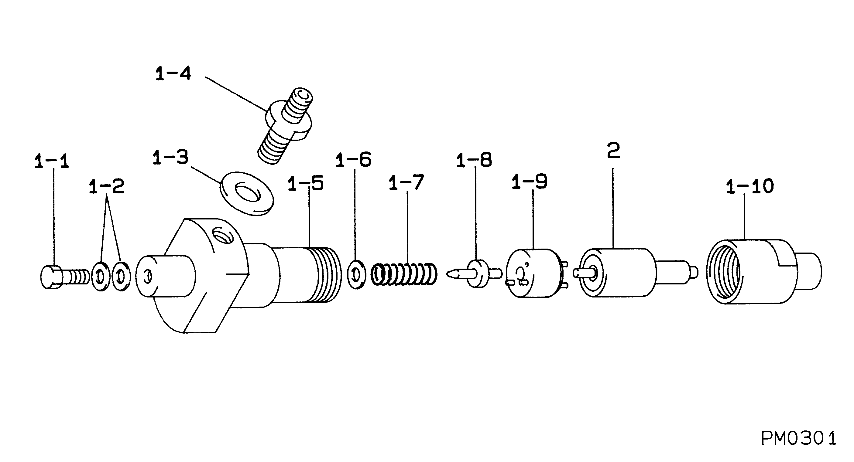
Information injection nozzle Denso
Nozzle Type:
ND-DLLA149S394
MITSUI DEUTZ INDUSTRIAL F/L912
Compare Prices: .
As an associate, we earn commssions on qualifying purchases through the links below

$48.68
17 Oct 2024
KR: Adabus
Long Durable Diesel Fuel Nozzle DLLA149S394 093400-0450 Injector Nozzle DLLA149S394 Fuel Nozzle for Hino H06B-T
Generic
Generic
$50.99
09 Aug 2024
RU: Udith
long warranty durable diesel fuel nozzle DLLA149S394 093400-0450 injector nozzle DLLA149S394 fuel nozzle For HINO H06B-T
Generic
Generic

$44.00
30 Mar 2024
CN: lutong part plant
Diesel Fuel Injectors Nozzle DLLA149S394 Injection Nozzles 093400-0450 Car Accessories Engine Parts 6pcs Fits for DEUTZ 912 913 FENDT Farm GT
DICSCL PARCS
DICSCL PARCS
Include in ##:
Cross reference number
Part num
Firm num
Firm
Name
093400-0450
0433271162
BOSCH
INJECTION NOZZLE
093400-0450
5621758
CAV
INJECTION NOZZLE
Information:
Install Water Pump
1. Put the gasket and water pump (1) in position in the timing gear cover. 2. Install the pointer and bolts to hold the water pump.3. Put the vee belts in position on the engine.4. Use a belt tension gauge such as Borroughs Tool Company Part No. BT-33-72C or an equivalent and make an adjustment of the vee belts. Tighten new belts until the gauge indication is 120 5. Operate the engine at high idle for a minimum of 30 minutes after Step 5. Make another adjustment of the belt tension. The correct gauge indication for used belts is 90 10. Tighten the bolts that hold the alternator.5. Fill the cooling system with coolant to the correct level.Disassemble Water Pump
a) remove water pump1. Hold the pump shaft in a vise as shown and remove the bolt and pulley (1). 2. Use tooling (A) and a press to remove the shaft, seal and impeller from housing (2) as shown.
The press must have a guard. The guard has been removed for photo illustration.
3. Remove bearing (3) from housing (2). 4. Remove spacer (4) from housing (2). 5. Use tool (B) to remove ring (5) from housing (2). Remove bearing (6) from housing (2).6. Use a press and tool (C) to remove the shaft and seal assembly from impeller (7) as shown. 7. Install the seal assembly and shaft in housing (2) as shown. Use a press and tool (C) to remove the shaft from the seal assembly. Assemble Water Pump
1 Install bearing (1) in housing (3). Use tool (A) to install ring (2) that holds bearing (1) in position. 2 Install spacer (4) in housing (3). 3 Make sure the outside diameter of bearing (5) and the bore in housing (3) are clean and dry. Install bearing (5) in housing (3). Fill the chamber area between the housing and outside diameter of bearing (5) with 7M7456 Bearing Mount. Remove the excess bearing mount from the housing. 4. Turn the pump housing over and make sure that the bores in the bearings and spacer are in alignment. Install the shaft through the bearings from the impeller side of the housing. The shaft to bearing clearance can be 0.018 mm (.0007 in.) loose to 0.008 mm (.0003 in.) tight. If it is necessary to use a press to install the shaft, make sure the inner races of the bearings have support. 5. Install pulley (6) on the shaft and tighten the bolt to a torque of 75 7 N m (55 5 lb.ft.). 6. Put a new seal assembly (7) on the shaft as shown.7. Use tool (B) and a press to install the seal assembly in housing (3). Do not use a hammer to install the seal. 8. Put tool (D) between impeller (8) and the pump housing.9. Use a press and tool (C) to install impeller (8) on the shaft until tool (D) can just be moved between the housing and impeller. 10. If